Ultrasound waves and propagation

It has been more than 100 years since ultrasound has been used for analyzing materials and echolocation. A bit later, it was adapted for medical diagnostics. Ultrasound became popular and widespread due to the number of benefits. Probably one of the essential features is that it is non-destructive. The other is simplicity and precision. Of course, when we talk about price and simplicity we have X-ray or tomography in mind. Ultrasound can be used in many areas and environments. You can measure geometrical properties of internal structures and physical properties like density and tension. In medicine, ultrasound visualization is mainly used as a non-invasive medical imaging technique using high-frequency sound waves to produce images of internal body structures. It is commonly used to view and diagnose conditions related to pregnancy, the abdomen, and the heart. The images are created by transmitting sound waves into the body, which bounce off internal structures and are detected by a transducer, then processed by a computer to create real-time images. Ultrasound is generally considered safe and painless and does not involve ionizing radiation.

Continue reading

Benefits of using multiturn potentiometers

Potentiometers are common electronics components that convert rotary or linear motion in to change of resistance. They can be found anywhere where some adjustments are needed, volume control, and joysticks. You can dive into the long theory about potentiometers, how they are made, what materials are used, and what output characteristics they have regarding rotation angle. As an electronics hobbyist and probably pro, you usually deal with two common types of potentiometers – standard pots with knobs and trim potentiometers. The first group of potentiometers is used where the user has to access the potentiometer when he needs to change one or another parameter like sound volume or screen brightness. They usually are more prominent in size and can be mounted vertically or horizontally to board. Also, they have a panel mount with the nut. This type of potentiometers needs to be mechanically stronger and resistive material more durable due to frequent use.

Continue reading

Building simple constant current power LED driver

Usually, when we need to drive low power LEDs, we don’t care much about power losses. What we do we add a current limiting resistor, and that’s enough. For instance, for 20mA LED, we choose between 300Ω-1kΩ resistor when powering from 5V. But a different situation is with power LEDs. The currents are much more prominent here, like 1A and more. Adding a resistor to limit the current isn’t an option because power losses become significant. Here you need a constant current driver to drive it safely without wasting energy. It happens that I have Cree XR-E Q5 XLAPM-7090 LED lying around. It requires a 3.7V driving voltage and can take up to 1A current. There are several light intensities given at specific currents:

Continue reading

Driving LED – things everyone needs to know

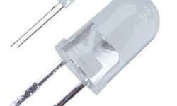
Light Emitting Diodes, more frequently known as LEDs, are semiconductor devices that convert electricity into light. It was hard to find a gadget or other device that doesn’t use LEDs. They are cheap, they are simple to use, and they are small. LEDs can emit different light colors depending on other chemical compound material in a semiconductor. LED symbol One and universal LED symbol is as standard diodes but with a couple of arrows indicating that it emits light:

Continue reading

Zener – one diode for many uses

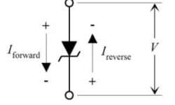
Zener diodes are specially designed diodes (heavily doped) that have low reverse voltage breakdown. Due to this characteristic, Zener diodes are connected backward to regular operation. If Zener is forward biased, it acts as an ordinary diode with a forward voltage drop at 0.6V. Zener diode backward voltage breakdowns may range from 2.4V up to 100V. Honestly speaking, if you need like 1.2V, then probably you need to connect two forward-biased diodes in series for 0.6V+0.6V = 1.2V drop.

Continue reading

Did I just increase DS1022CD bandwidth four times?

Probably you are already familiar with the famous DS1052E hack where guys were able to double and even triple bandwidth. It happens that on my table is DS1022CD scope with 25MHz analog bandwidth. And this hack doesn’t apply to my model. We all know that the same series Rigol oscilloscope models tend to have identical hardware, whether 25MHz, 50MHz or 100MHz analog bandwidth. Of course, the sampling rate (400MHz) stays the same. So it all lies in the software. I felt that someone would figure out how to do this with this pretty old oscilloscope. And here it is – a hackaday pointed to a piece of great news – a simple way of changing the model from DS1022CD to DS1102CD, which converts analog bandwidth from 25MHz to 100MHz. This is quite a step without spending a penny. Andreas Schuler (aka Krater) shared a simple method of doing this without using any serial interfaces and firmware updates. By following his step by step guide, you can do this as follows:

Continue reading

Diodes – how to choose one

Diodes are semiconductor devices commonly used for many purposes. In general, you can imagine a diode to be a valve that passes current in one direction and stops it from flowing back. The first thing that comes to mind – this might be a good choice for reverse voltage protection. In reality, things are a bit different. First of all, diodes aren’t perfect devices. They have a so-called forward voltage drop, which is about 0.7V for standard diodes. If inserted diode into the power supply, say 5V, the after protection you will get 4.3V where part of voltage is lost in the diode. If you want to go this way, choose the Schottky diode instead, which has a smaller forward voltage drop. A forward voltage drop occurs when the diode is forward biased what means current flow from anode to the cathode.

Continue reading

Thoughts on interfacing piezo vibration sensor

piezo vibration sensor test with oscilloscope

Some time ago, I purchased a MiniSense 100 Vibration sensor. I probably had some project in mind, but it happened that it dived into drawer among other “to do” things.  I thought it’s time to try a few things with it. Piezo sensor MiniSense 100 is very sensitive with a pretty good frequency response and is linear (±1%). As you can see, high sensitivity is achieved with a 0.3-gram inertial mass at the end of the film. As there is a hole in the mass, you probably can screw in an additional mass and increase sensitivity even further. Probably there is no need to explain where such a sensor would be helpful. These could be vibration/ motion sensors, impact sensors, and other areas where motion and acceleration are involved. Usually, sensitivity is 1V/g. Where g is standard gravity or standard acceleration due to free fall and is equal to 9.80665m/s2. As a mechanical device, it also has a resonant frequency of 75Hz. At this point, sensitivity reaches 5V/g.

Continue reading

Building simple power supply from theory to working example

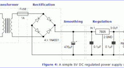
A power supply is an essential part of every electronic device. The whole system relies on it. If a power supply fails – the device dies too, and there is a chance that sensitive parts may be damaged. Power supply solutions vary from device to device. They may work using different techniques depending on needs. Tim has described probably the simplest power supply solution, which converts Alternating Current (AC) to Direct Current (DC). The supply circuit consists of well-known parts – transformer, which transforms voltage from 230V AC to 12VAC, follows diode bridge rectifier, smoothing using large caps and regulation with standard 7805 voltage regulator. Such a solution proved itself in many designs. It is simple, cheap, and builds fast. Tim put everything in the short and informative post without overhead information. Following it, you will be able to construct a 5V DC power supply in an hour.

Continue reading

12V solar charger using LM317

[Alex] decided to build a solar charger for his car battery. He had an 18V solar panel able to provide up to 83mA. You cannot connect the panel directly to the battery because charging voltage cannot exceed the allowed safe limit, and also solar panels may become a load for the battery in a dark time, and this way discharge it. So he ended up with a simple circuit utilizing LM317 and a couple of resistors setting voltage so that battery would be charged at the recommended 13.2V. To prevent back supply, a Schottky was used. Of course, it adds some voltage drop (0.7V worst case). This was taken into account while calculating voltage adjusts resistor divider. As a test [Alex] left a solar charger for three days connected to his battery, and it charged up to 12.35V which is about 75% of capacity. Not bad at all.

Continue reading