I got few questions from our readers about the bit-band feature in ARM Cortex microcontrollers. It may seem to be a prominent topic, still may lead to come confusion while using bit-banding. So let’s look at this feature a little bit closer.
Why use bit band?
Simply speaking Bit banding method allows performing atomic bitwise operations to memory areas. Why use bit banding? The most straightforward answer is because ARM Cortex doesn’t have something like BIT CSET or BIT CLEAR commands like most of the 8-bit microcontrollers do. So this is somewhat a workaround solution. Another question may rise – Why not using the read-modify-write method? Again this method is not reliable in some cases. For instance, f there is an interrupt during this operation; it can cause data corruption. Other situation may occur in embedded OS when different tasks may modify the same memory location. So we want a method that allows setting or clear individual bits with a single instruction. This is where the bit band method helps.
If you open any ARM Cortex documentation or datasheet, you will find that bit-band can be performed in two memory regions – the first 1MB SRAM region (from address 20000000h to 200FFFFFh) and the first 1MB peripheral region (from address 40000000h to 400FFFFFh). What does this mean? This means that bitwise operations can be performed to RAM and peripherals like ports and other peripheral registers.
How does the bit band method work?
The bit band mechanism works by using a separate memory region called the bit-band alias. Alias regions are located far from available RAM or actual peripherals.
As you can see for RAM, this region starts at address 22000000h, from 31MB. This is a safe location as ARM internal SRAM will not likely reach 32MB. The same situation is with the peripheral region. It also starts are a 31MB location (at address 42000000h).
Using the bit-band alias memory region, we can access individual bits of RAM or peripherals. Each bit in memory is addressed using a 32-bit bit-band address in the alias memory region.
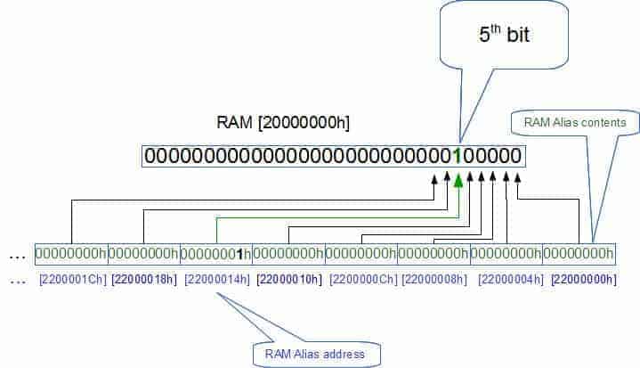
Let’s say you want to change the 5th bit of RAM contents stored at address 20000000h. Since this is the first memory address from the alias region, we can find an alias address pretty quickly. The first alias address is 22000000h, which is the address of the first (actually 0) bit in RAM. The second 1st bit in the alias has an address of 22000004h (remember each 32-bit word address is increased by 4), the second bit is addressed with 22000008h, and so on. So the fifth bit has an alias address 22000014h. If you want to write or read a bit from the SRAM word, you need to write or read 0-bit from the corresponding bit band address. In other words, you need to write 1 to RAM address 22000014h to set the 5th bit in RAM location 20000000h. This applies to bit read operation as well.
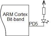
How to calculate alias address to any bit in RAM location? For this, you can do a simple calculation. Let us say we want to access peripheral bits. We know that the peripheral area starts at address 40000000h. So we call this address as Peripheral Base; then peripheral Alias Base is 42000000h. Let’s say we want to write 1 to PORT D 5th pin 1. We need to set this bit to 1; From the memory map, we find that the PORT D output register address is 4001140Ch. So this is 1140Ch – the byte in peripheral memory. Since each byte in memory offsets address by 20h in the alias memory region, we can calculate that the PORTD output register alias starts at 1140Ch * 20h. Then we need to add a 5th bit: + 5×4. So our alias address for PORT D output register GPIOD_ODR pin 5 is:
42000000h + 1140Ch * 20h + 5 * 4 = 42228194h
In C program we can define this bit as a pointer and use it to set or clear this bit:
#define PortDBit5 (*((volatile unsigned long *) 0x42228194))
Then anywhere in the program when you need to set this bit to 1 you can write:
PortDBit5 = 1;
Or write zero:
PortDBit5 = 0;
In C program you can prepare a MACRO to calculate the bit-band location for particular bit location.
#define PERIPHERAL_BASE 0x40000000
#define BITBAND_PERIPHERAL_BASE 0x42000000
#define BITBAND_PERIPHERAL(a,b) (BITBAND_PERIPHERAL_BASE + (a-PERIPHERAL_BASE)*0x20+(b*4))
//port D output register address
#define GPIOD_ODR 0x4001140C
//create a pointer to bit 5 in bit band location
#define PORTDBIT5 (*((volatile unsigned long *)(BITBAND_PERIPHERAL(GPIOD_ODR,5))))
//use it somewhere to set bit to 1
int main()
{
//...
PORTDBIT5 = 1;
}
Now you see how it’ simple. If you used to read modify write operation, you would risk getting data corruption in some cases. Also, read-modify-write takes about twice as long as using bit band based set and clear. If you need to set multiple bits at a time, then you lose performance with bit band operation. So if there is no risk of data corruption (like interrupts won’t tend to change the same data), then read-modify-write is better to use when multiple bits are changed. The wise use of this method can boost some performance on a more significant scale.
Also, it is worth to mention that bit band operations can be performed for half-word and byte-sized memory locations. Then the difference is in the alias address algorithm. Instead, you would use multiplier 2 for half-word and 1 for byte.


