USB powered power amplifier for your PC
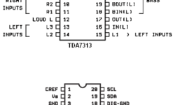
I faced this article when I was looking for a simple solution to increase the output of my PC’s integrated sound card. The sound level of it decreased, so I can’t normally listen to my headphones. So this article is about how to increase your PC sound card’s power by using a minimal amount of parts and a USB power supply. This might be a good solution for all of those who have a PC with an integrated sound card into the motherboard. The main problem is that the outputs of such sound cards are for active acoustic systems; this means that speakers must have a power amplifier built-in. If you decide to connect headphones sometimes, it might not be enough to provide the required sound level. If you are an electronics amateur, you can solve this very easily. You may build your simple power amplifier by using well known Philips operational amplifiers. Let’s say we use the TDA7053 amplifier. The TDA7053 is an integrated class-B stereo power amplifier in a 16-lead dual-in-line (DIL) plastic package, which requires a minimal amount of external parts. This is a straightforward solution for easy, quick, and quality design. One of the board solutions…
Set up AVRStudio to use AVR-GCC compiler
After the release of AVRStudio4, there is possible to integrate the AVR-GCC compiler into it. As you know, AVRstudio is a powerful tool that has an assembler compiler- debugger, programmer, etc. Integration of AVR-GCC makes this tool a much more powerful and more complete playground for developers. A plugin built-in AVRStudio detects the AVR-GCC compiler by itself, so you don’t have to bother how to tie them together. And here we go – full set of good tools comparable to commercial. The convenient user interface, automatic makefile generation, visual debugging by watching processors register, or even you can flash the chip. How to set up the working environment? This is simple. First of all, you have to download WinAVR20060421 and install it on your machine. Then download AVRStudio Version 4.12 and service pack 3 and install them on your PC. And… that’s it. You are set. Now open AVR Studio and select menu->Project Wizard->New project. In a Welcome AvrStudio4 Screen, select Project Type AVR GCC, enter a project name, select Create Initial file if you want to initial c file to be created. Select Create Folder to put project files in a separate folder. Enter an initial c file name.…
Interfacing PC keyboard to AVR microcontroller
Properties: Interface AVR to standard PC AT keyboard; Only two I/O lines were used. One line is also connected to the external interrupt pin of AVR; No external components are needed for the interface; Included C source reads from keyboard interface and converts to serial In many situations, you need some human interface for your microcontroller project. In this example is interfacing AVR microcontroller to standard PC AT keyboard described. Physically interface looks as in picture bellow: In a keyboard interface, signal lines are an open collector with pull-up resistors.
Clockless CPU design
Clockless CPUs are so-called asynchronous CPUs where are not clock generator needed, which clocks every synchronous operation. Asynchronous processors give results, not after a defined number of clocks, but after it finishes operations. This is a key to effective energy usage, and asynchronous processors generate less noise than synchronous. Asynchronous processors have couple advantages against synchronous: Components can run at different speeds inside a clockless CPU, while clocked CPU components are tied to a clock generator. Clockless CPU operation stages don’t depend on clocks and can be finished faster than normal, and there is no time gap between stages as there is no need to wait for the next clock cycle. For instance, it can show the operation results rather than waiting for the next clock cycle like it is in a synchronous CPU.
Embedded RTOS System
RTOS ( Real-Time Operating system) is a programming environment that interfaces hardware and desired tasks. RTOS usually has a built-in set of services (interfaces and functions) that allow interaction between tasks and hardware. Because most low-level functions are performed by RTOS, the realization of programs becomes much easier. What is the difference between Embedded RTOS System and a regular OS (Operating System)? The main difference is that RTOS performs tasks according to reaction time on one or another event. Many microcontrollers have the ability to support one or another Real-Time Operating System.
Connect 6 LEDs using 3 microcontroller pins
Sometimes you need more than you have. I am talking about microcontroller pins. You have to connect 6 LEDs, but you have only 3 microcontroller pins available. To use another microcontroller isn’t always a solution using decoder circuitry isn’t necessary as well. There is a simple hint on how to do this: Connect diodes to the microcontroller as follows: Now, look – if you set one pin to “1” and second to “0” (leave third pin high state – as input pin), then only one led lights on. You can light two LEDs by setting the third pin as an output and state “1” or “0,” which depends on which LED you want to light.
Testing Your Embedded System
Every time you are making some circuit or more complex system, you always do some testing to ensure that your electronic creation is working properly and exposing it to publicity. Let’s say you are constructing some robots. Then a typical list of the testing task may be as follows: Stability tests using various working modes and critical supply voltages (like 4,75 and 5,25V); Start-up testing purpose is to check system readiness to accept commands after power-up; Checking correctness of executed commands; Checking correctness of sensors; Sometimes you will need to prepare good documentation where every node reliability is calculated. Also, testing methods of each node may be included in the documentation. Of course, many devices may work in a wider range of supply voltages, but there are always some electronic components that need more than 5% stability.
Microcontroller Brown-out detection
Mostly all microcontrollers have built-in Brown-out Detection (BOD) circuit, which monitors the supply voltage level during operation. BOD circuit is nothing more than the comparator, which compares supply voltage to a fixed trigger level. If the microcontroller doesn’t have an On-Chip Brown-Out detector, then there can be an external circuit used : In the image above, there is a discrete brown-out detector circuit. There are particular IC where additional delay circuitry and hysteresis used to normalize supply voltage may take some time in a real word. Such ICs are cheaper than one built from discrete components.
Radio Frequency Identification RFID
There are two types of RFID devices: Active and Passive. Active devices have a power source built-in, which supplies the transmitter. The transmitter is triggered by sending the signal to an RFID device. These devices have their own code and can transmit signals in desired time intervals. Active RFID devices are good in defining locations of objects or sending some information about a particular place (RFID-based location determination). Active RFID devices use high frequencies (455MHz, 2,45GHz, or 5,8GHz) – working range about 20 – 100 meters. The most common are passive RFID. They don’t need a power source. Passive RFID devices are low frequency(124 – 135kHz – low) and high(13,56MHz – 960KHz – high; 2,45GHz – UHF). The working principle of low and high-frequency devices differ. Simultaneously, low-frequency readers generate a magnetic field that induces a current in the RFID device antenna. The chip inside the RFID device modifies this magnetic field, which is reread by the reader. The working distance of such a device is about 35cm.