Cheap Arduino compatible boards are same as original
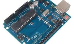
Probably you have noticed that Arduino is spread worldwide. It would be ridiculous to see one manufacturer producing them. The Arduino group produces an original board that is named Arduino. This is their trademark. But being an open-source product, Arduino has become popular in almost all workshops, so demand is enormous. Since building plans are public, other electronics manufacturers started building Arduino-compatible boards. These are the same Arduino boards but with Arduino’s name and logo removed. It is 100% compatible with standard Arduino that works with software tools, extensions, and modules.