AVR microcontroller interrupts using WINAVR
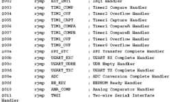
I can’t imagine a microcontroller without interruptions. Without interrupts, you would have to make loops to check if one or another event occurred. Polling has many disadvantages like programs have to make loops, which takes valuable microcontroller resources. These resources may be used for other data processing tasks. This is why the microcontroller comes with built-in interrupt support. Instead of checking events, the microcontroller can interrupt normal program flow and jump to interrupt the service subroutine. During an interrupt, the microcontroller stops the task at the current point, saves necessary information to stack, and gives resources to interrupt the subroutine. When interrupt subroutine finishes, and then normal program flow continues. In assembler your program would start with interrupt table: After the table goes the main program (RESET) and other interrupt subroutines where the program jumps after the interrupt occurs.