Use of Nanotechnolgy
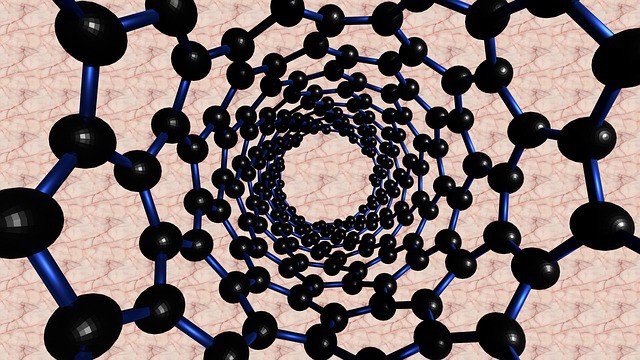
People are very much astonished by the fact that people can engineer at the level that is not at all imagined. Nanotechnology provides the user to play with a variety of components present in the world. The nanoscience engraves certain unique features associated with the development of science. It revolves around certain intricate topics such as manufacturing at the nano level and then engineering components at the nano level. This may involve an improved skillset from the working community. The works of various researchers involve the use of nanotechnology in day to day life. The people worldwide may appreciate the use of Nanotechnology in production of carbon tubes used for various engineering applications if it is feasible. But it is known that nanotechnology’s use to produce such a small component is practically impossible, but this statement is proved wrong in recent years.