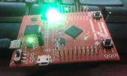
Implementing buttons on STM32F103ZET6

Last time we have made a good starting point with setting up a project template for the STM32F103ZET6 development board using GNU tools. Using the same project template, we can move forward and start programming other elements. This time a quick note about adding a button library. This is a modest implementation that initializes port pins and then reads their status. The Development board is equipped with four user-programmable buttons named WAKEUP, TAMPER, USER1, and USER2. We will not care about the meaning of names; use them as general-purpose buttons for now.

Continue reading

Driving LEDs with LPC2148 microcontroller

The LPC2148 development board is a mighty board with an ATM7TDMI series microcontroller considered an old guy compared to Cortex ones. But still, these are widely used and are powerful. The Development board has some handy features installed. 12MHz crustal allowing to run the processor at full 60Mhz speed. Couple RS232 ports, VGA connector, PS/2 connector for keyboard or mouse, 20-pin JTAG, SD/MMC slot, USB B-type, 8 LEDs driven with a serial-in parallel-out shift register, 2×16 LCD, buzzer, audio jack with an amplifier, two programmable buttons, and 256Kb of I2C interfaced EEPROM. The microcontroller itself has 512KB of internal flash and 32+8KB of RAM. All ports are accessible, and any external hardware can be disconnected with jumpers. This is a great board for prototyping and end application.

Continue reading

LED blinky demo on STM32F103ZET6 development board

I found some time to play with the STM32F103ZET6 development board and decided to set up a simple project for it. The trickiest part of this is to set up a project environment that would serve as a template for the following developments. Many ARM developers chose the CodeSourcery Lite edition toolchain. It has full command line functionality – this is what we usually need. If you want some alternative – you can select gnu yagarto ARM toolchain, which is also great and free. No matter which tool you select, the code will work on both. Let’s stick to CodeSourcery. Just download it and install it on your PC. As we said Lite version supports only command-line tools – we need an interface for it. Eclipse IDE is one of the favorite choices, so that we will grab this one too. Yagarto website has an excellent tutorial on how to set up the Eclipse IDE in a step-by-step manner. We won’t go into details with this.

Continue reading

FreeRTOS on AVR with external RAM

AVR microcontrollers aren’t the best choice to run the FreeRTOS scheduler due to low on-chip RAM. Atmega128 has only 4K of RAM, so this limits the FreeRTOS functionality to very basic. This problem can be solved by adding extra RAM, which may be connected to an external memory interface. We have already built an external memory block of 8K previously to test it with FreeRTOS applications. Let’s continue with our previous code, which runs several simple tasks (button state reading, LCD output, and LED flash), and we can add more to it. We are going to set up an external RAM for storing heaps. This will allow the storage of large data buffers without worrying too much about heap and stack overlaps.

Continue reading

New STM32F103ZET6 development board with 3.2″ TFT Touch LCD

The latest development board has just arrived. I thought it would be nice to push things more towards the ARM cortex-M3 playground. This an STMicroelectronics STM32F103ZET6 ARM Cortex – M3 MCU based development board with a 3.2” Touch LCD screen. This is a high – density performance line 32 -bit MCU featuring internal 512K of FLASH memory, 64K of RAM. It is rich in peripherals like USB, CAB, 11 timers, 3ADC, and many communication interfaces. The microcontroller seems to be powerful enough to run quite intensive tasks, but more memory is populated on board. Additionally, there are:

Continue reading

Running multiple FreeRTOS tasks on AVR

In the previous post, we just run a single task. Running RTOS with a single task has no meaning at all. This can be quickly done with a conventional program. But what if we need to have more separate functions. To execute them at exact timing would require a separate timer or interrupt. But microcontroller cannot guarantee an interruption for every task. This way, it is hard to make code modular, and testing can be painful. Using RTOS solves this kind of problem. It allows programming each task as an endless loop. Kernel scheduler takes care of assuring each task gets its chunk of processing time. Additionally, it does bearing the priority systems – more critical tasks are executed before less important ones. Let us go further with our example code and add more tasks to our FreeRTOS engine. We already have an LED flashing task that toggles LED every second. Additionally, we are going to create another task that checks the button state. Also, we are going to send some information to the LCD. As always, let’s take care of drivers for all of them.

Continue reading

Using FreeRTOS kernel in AVR projects

FreeRTOS is known as Real-Time Operating System. It would probably be too dare to call it real-time-os, preferably a real-time scheduler where applications can be split into independent tasks that share complete processor resources by switching them rapidly. It. It looks like all functions are executed in parallel. This feature is called multitasking. There are many debates on using RTOS on AVR microcontrollers as they are arguably too small for the running scheduler. The main limitation is a small amount of ram and increased power usage. If you use lots of tasks in the application, you will probably run out of RAM to save context when switching between tasks. Consider FreeRTOS only if you use larger scale AVRs like Atmega128 or Atmega256. Indeed you can find smaller schedulers that are specially designed for smaller microcontrollers, even tiny series. On the other hand, if you master FreeRTOS, it can be used with multiple microcontrollers like ARM Cortex, PIC, and various compilers, including IAR, GCC, and Keil Rowley, Attolic. And the main reason to keep an eye on it – it is free. Probably it would take lots of time and space to go through RTOS theory. Some great information can be…

Continue reading

Can vs LIN bus interfaces in automotive electronics

Modern cars have more electronics than you can think of. Almost every vital part has tons of sensors on it with a dedicated computer called ECU (Electrical Control Unit). Usually, there are from several up to hundreds of ECU’s in a single car. Especially luxury ones. All modules have to work as an organized unit. So this is where a reliable connection interface is needed. Probably you’ve already heard of CAN bus (Controller Area Network). It is a standard bus interface used in most vehicles where the board computer communicates with separate control ECUs taking care of the engine, gearbox, climate, security alarm, and safety bags. CAN devices are connected by using twisted pair signal wires that are more resistant to noises. Signals usually operate at the 5V level. The transfer speed can reach up to 1Mb/s for 40m cable lengths.

Continue reading

How to drive servo motor control with AVR microcontroller

Servo motors are so-called “closed feedback” systems. This means that the motor comes with a control circuit inside, which senses if the motor mechanism is in the desired position. If not, it continuously corrects an error until the motor reaches the angle. Servo motors are widely used in robotics, remote-controlled planes, vehicles, and many other industrial machines. They come in many shapes and sizes, but they all operate in almost the same way. Usually, servo motors are controlled by a computer, microcontroller, or even a simple timer circuit. How Servo Motor Control Works Usually, servo motors are put in the plastic box, but inside there is a whole system: motor itself, gears, and motor driving and control circuit. The gears reduce motor speed but increase torque. As we mentioned, servos work with a closed feedback loop when the potentiometer is connected to a mechanical shaft and senses the angle of turn. The potentiometer voltage directly indicates the grade of twist. The potentiometer signal goes to a digital controller of the motor, which powers the motor until the potentiometer reaches the desired angle, then the logic circuit shuts the motor.

Continue reading

How to write an LCD menu for AVR in C

Let us write a simple LCD menu for AVR. I am using four buttons: 2 for menu scrolling up and down and two for changing submenu parameters. As the output indicator, I am using three LEDs that flash according to the menu’s parameters. Button states are captured by using timer0 overflow interrupts. The circuit is elementary:  I have excluded the power circuit for simplicity, just left the main parts: LCD, LEDs, and buttons. This circuit works well with the Proteus simulator as it is. The Proteus circuit is attached to the project archive. My idea is to store menu strings in Flash memory without occupying MCU RAM. This way, menu items are limited only by Flash memory, not by RAM.

Continue reading