LPC2000 MCU memory acceleration module

We know that the ARM MCU core can run at a speed line 60Mhz or even more than 100Mhz. But usually, the ARM program is located in Flash memory. But flash memory execution speed can reach only up to20MHz. Practically speaking, Flash memory is 3 – 4 times slower than ARM core speed can run. Of course, one of the workarounds could be loading critical program parts to RAM, but RAM is a limited resource – we cannot locate all programs to RAM as needed for data storing and so on. So second option is to have on-chip cash memory, which stands between CPU and memory. Well, LPC2000 and other ARM7 family has reduced cache module so-called Memory acceleration module (MAM). Without going too deep on how MAM works, I can say that acceleration basically works by loading four ARM instructions simultaneously from Flash (Eight THUMB instructions). If an ARM is running at a speed of 60MHz, then there would be 3 access cycles to flash needed. MAM loads these instructions at one cycle. Usually, the MAM module is disabled after MCU reset. There can be three working modes of memory Acceleration Module:

Continue reading

ARM MCU Memory Map

Arm microcontrollers have linear memory organization. Starting from 0x00000000 address to 0x40000000 is Internal Flash memory location. From 0x40000000 to 0x7FFFFFFF is on-chip RAM memory space. As we know many ARM families like LPC2000 series MCU is preprogrammed with flash boot-loader and ARM real monitor debug, so both are placed at location starting from 0x7FFFFFFF to 0x80000000 memory location. Address space from 0x80000000 to 0xE0000000 is reserved for external memory.

Continue reading

Schmitt trigger VS simple inverter

Schmitt trigger is a special logical element adjusted to work with analog input signals. The primary purpose of Schmitt triggers was to restore the shape of digital signals. Because of the transmission line effect, digital shape transforms from square to trapezoid or triangle or more complex signal. Of course, during transmission, signals become noisy and distorted. Schmitt trigger is a comparator circuit, but positive feedback results in hysteresis and memory effect. Comparing to simple logical elements, Schmitt triggers have two threshold levels. Between these threshold values U1 and U2, the state of output doesn’t change the so-called hysteresis. Such an effect stabilizes output against rapid triggering by noise. Bellow is two characteristics compared of simple logical inverter and Schmitt trigger inverter:

Continue reading

Marking of Digital IC chips

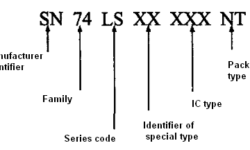
There are currently huge amounts of different digital IC chips available in the market, starting from the simplest logical elements and ending with processors and gate arrays (FPGA). Of course, there also are lots of IC manufacturers offering IC’s. Many of them are specialized and won’t be reviewed here. Let’s limit ourselves to smaller, more general digital chips, basically TTL 74series. This series is produced by many manufacturers like Texas Instruments (TI).Common marking: Manufacturer identifier indicates the manufacturer name;

Continue reading

VGA to X-Y-Z scope converter

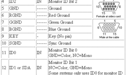
This is a fun project I found on Jon’s antique radios web-page. He has managed to convert the VGA output signal from PC to X Y X oscilloscope signal. Converting the VGA RGB signal to a synchronized oscilloscope input signal is pretty easy because VGA has two sync signals separate from RGB signals. Look at pin-out of VGA cable: Sync signals make things much easier as there is no need for additional sync signal generators – thus circuit becomes pretty simple without any programmable components:

Continue reading

ATTiny2313 Monitor tester

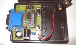
This project was born for repairing broken PC monitors. This allows avoiding using a computer while testing monitor patterns. The Tiny monitor tester uses ATTiny2313 AVR MCU running at 20MHz speed. Such speed allows running synchro H and V signals directly from MCU ports. Also circuit converts R, G, B signals to analog using a simple R-2R resistor network. ATTiny2313 Monitor tester:

Continue reading

ARM7 MCU Bus structure

ARM MCU has multiple bus structures. There are two types of Busses in ARM7 microcontroller – Advanced High-performance BUS (AHB) and VPB bus. AHB is a fast bus that is clocked directly by PLL and works simultaneously as the ARM core. So to the AHB bus, the ARM core, and Interrupt controller is directly connected while other peripherals are connected through the VPB divider. VPB divider can divide the speed of AHB by 1, 2, and 4. so this means if the VPB bus divider will be set to 4 and the CPI core speed will be 60MHz, then the MCU timer will run at speed 60/4=15MHz. C code snippet of VPB speed setting:

Continue reading

Debugging tools for ARM7

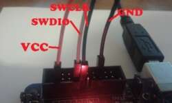
Usually, one solution of debugging is to run compiled code on a PC simulator. You can download a limited version of the instruction set simulator from Hitex for free. Of course, better simulators aren’t for free. More advanced simulators you can purchase at Keil. More advanced, I mean that there is the ability to simulate peripherals by additional scripting and so on. But again, simulators are virtual tools, and usually, it is hard to simulate real-world events. Once you face this problem, you are going to switch to real-world simulation using JTAG.

Continue reading

RS232 emulates I2C for 24cXX memory programming

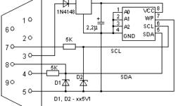
Sometimes you need a quick and easy solution for programming serial EEPROM memory chips. I think the easiest and well-known method is to use a simple programmer adapter with very few components: This adapter is connected to the RS232 port, and there is no need for an additional power supply as it comes from the PORT pin. The adapter is compatible with JDM Programmer so that you can use its programming software like IC-PROG. Just make a couple of settings, and you are ready to go:

Continue reading

Desoldering Atmega128 using a lighter

I heard about this method and decided to try it with my board. I needed to replace the Atmega128 chip but didn’t have hot air solder for desoldering IC. I tried this weird desoldering technique, and I can say that I was satisfied. Tracks and other parts weren’t damaged. The Atmega128 board is working again as before.

Continue reading