
LPC2000 microcontrollers have at least two 32 bit timer counters. Let’s take the LPC2148 microcontroller, two general-purpose 32-bit timers that are identical except the peripheral base address. These timers are for general purposes that can perform timer and counter operations. Timers have many features:
- Programmable 32 bit pre-scaler;
- Up to four 32 bit capture channels that can take snapshots with interrupt generation ability;
- Four 32 bit match registers that allow generating interrupt on the match, generate interrupt and stop the timer, generate interrupt and reset the timer;
- Up to four output pins that can be set LOW/HIGH/TOGGLE on compare match;
Timer’s nature is to count cycles of the peripheral clock, which depends on VPB divider value and can be equal to the processor clock (CCLK=PCLK) or be twice or four times slower. Timer counter block can select a capture signal as a clock source instead of PCLK.
As we mentioned, timer0 and timer1 have a connection to real-world ability. One type of connection is for Input events and the other for output.
Input pins are marked CAP0.3…0 for timer/counter0 and CAP1.3…0 for timer/couter1. Through these capture pins, signal transitions can be sensed, and together with configured capture registers, interrupts can be generated. As we see, each timer has four capture pins assigned. So if more than one capture pin is selected, then the pin with the lowest number of pins is used.
Output pins are used together with match registers and can generate signal toggle, go low, go high or do nothing on compare match. Each timer has four pins to match MAT0.3…0 for timer/Counter0 and MAT1.3…0 for Timer /Counter1. Output pins can be configured to work in parallel, providing the same function.
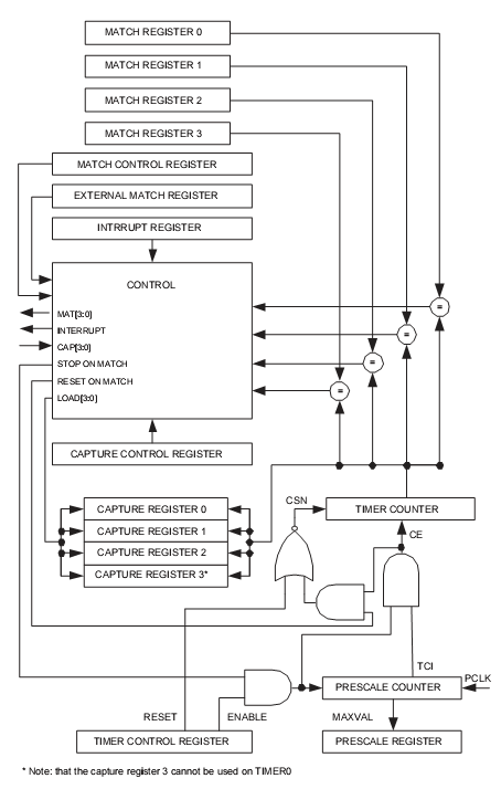
If you look at the diagram, you can see that the PCLK signal goes through the 32 prescaller counter. Prescaller counter is a register that increments on each PCLK cycle. When the value reaches a max value set in the prescaller register, it resets, sends a count to the timer counter, and starts counting again from zero.
The timer counter control register (TCR) has only two bits that enable/disables timer counting and resets the timer.
As we see in the picture timer has 4 capture registers. Each capture register has an associated capture pin. When a capture event occurs (rising, falling, or both edges), the event on the pin triggers a capture event. During the capture event current timer value is stored to the associated capture register, and if configured – an interrupt can be generated. This functionality allows calculating time between two events what leads to pulse width measurements or frequency counters. Capture events are controlled via Capture Control Register(CR)
Timers also have four match registers that are associated with match pins. In match mode, the counter value is compared to the match register’s value, and if values match event is triggered(external pin toggle, set, clear, no action). The timer can be reset, stopped, or interrupt generated. Match events are controlled via Match Control Register(MCR).
The page is very informative.I would request you to post the C code for generating delay using timer0 and timer1 in lpc2103 processors