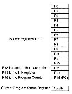
ARM has 31 general purposes 32-bit registers where 16 of these are visible at any time. Other registers are used to speed up the processing of exceptions. There also are 6 32bit wide status registers. Let’s see how it looks like. Registers are arranged in partially overlapping banks with a different register ban of each MCU mode. As I mentioned, 15 general-purpose registers(R0 to R14) and one or two status registers and PC are visible at any time.
Basically, R0-R12 registers are user register, that doesn’t have a special purpose. Registers R13 – R15 has special functions. R13 is used as stack pointer (SP), R14 is used as link register (LR), and R15 is as the program counter (PC):
Additionally, a Program status register CPSR contains several flags of program status and control information. All modes have saved program status register SPSR of CPSR register except User/system mode.
- The N bit is the “negative flag” and indicates that a value is negative.
- The Z bit is the “zero flag” and is set when an appropriate instruction produces a zero result.
- The C bit is the “carry flag,” but it can also be used to indicate “borrows” (from subtraction operations) and “extends” (from shift instructions (LINK)).
- The V bit is the “overflow flag,” which is set if an instruction produces a result that overflows and may go beyond the range of numbers represented in 2’s complement signed format.
- The I and F bits determine whether interrupts (such as requests for input/output) are enabled or disabled.
- The T bit indicates whether the processor is in “Thumb” mode, where the processor can execute a subset of the assembly language as 16-bit compact instructions. As Thumb code packs more instructions into the same amount of memory, it is an effective solution to applications where physical memory is at a premium.
- The M4 to M0 bits are the mode bits. Application programs normally run in user mode (where the mode bits are 10000). Whenever an interrupt or similar event occurs, the processor switches into one of the alternative modes allowing the software handler greater privileges concerning memory manipulation.
ARM7 MCU has six operation modes, and each mode has its own register configuration. For instance, FIQ interrupt mode has duplicated R7 – R12 registers, and the program doesn’t have to preserve registers into the stack. And, of course, R13 – R15 registers are duplicated in each following mode. Other registers (R0 to R7) are un-banked what means they are physically the same and accessible in all modes.
ARM7 is a load-and-store architecture. Before processing any instruction, the data must be moved from memory to a set of registers after execution data is stored back into memory.


