
All-flash memory of LPC2000series microcontrollers is arranged as two interleaved banks. But user sees it as one memory space. All-flash memory appears to the user as series of 8K sectors. These sectors can be written and erased individually. There are several methods of how flash memory of ARM can be programmed.
- One and easiest way is to use a built-in bootloader. The code is downloaded by bootloader via USART0 to RAM, and then it is programmed to Flash. There is a tool for this – Philips ISP Utility that works under Windows environment.
- Another method is to use JTAG to program flash memory. This method is usually used from debugging environment. JTAG is faster than ISP – reaches up to 400kB/s.
- The third method is the ability to reprogram Flash memory sectors using application commands that are on-chip. This feature is handy for updating code in a given section. This is so-called Field Updating.
LPC2000 bootloader
After each reset microcontroller is mapped to boot mode, reset vector jumps to the bootloader entry point at address 0x7FFFFFFF. After the program enters the bootloader, there are many checks performed. First of all, it checks if it was a hard or soft reset. If it was a hardware reset, then the logic level of P1.4 is tested. If it is LOW, then the Bootloader command handler starts. If a software reset occurred (watchdog or P1.4 is high), then it means that there is no programming request. Every time the program starts being executed, the bootloader checks a valid program in flash. This is done by checking the program signature (every program has it). Signature is word width and stored in an unused location in the ARM7 vector table at address 0x00000014. Program signature is two’s complement of the checksum of the LPC2000 vector table. Without the program signature, the user program wouldn’t run.
Few words about LPC2000 flash ISP utility
LPC2000 flash utility is a software that is used to program LPC2000 series ARM microcontrollers:
LPC2101, LPC2102, LPC2103, LPC2104, LPC2106, LPC2106, LPC2114, LPC2114, LPC2119, LPC2124, LPC2129, LPC2131, LPC2132, LPC2134, LPC2136, LPC2138, LPC2141, LPC2142, LPC2144, LPC2146, LPC2148, LPC2194.
Programming is done using an RS232 serial port. As we mentioned, LPC2000 series microcontrollers come with a boot-loader used to program Flash or RAMs and perform other operations like erasing and editing memory sections. The bootloader has an algorithm that detects incoming ISP connection, detects baud rate automatically.
When starting ISP after reset, P0.14 has to be pulled down what means that microcontroller is ready to accept ISP commands. Otherwise, keep the P0.14 pin pulled high to avoid unintended ISP entry.
Lets take a look at main screen of LPC2000 flash utility:

First of all, you have to power up your target board, connect the serial cable to the PC. Then in a screen, select COM port number and baud rate. If you use automatic ISP entry mode, then check DTR/RTS. The Target board has to be designed to control DTR and RTS lines (P0.14 pin and RESET pin). Otherwise, use manual entry mode.
Enter crystal frequency of target board in kilohertz. After this, press “Read Device ID” to make sure that the device is detected correctly. Part ID and boot-loader ID is detected. If successful, you can now start programming your microcontroller.
Open the hex file and press “upload to flash” to send code to the microcontroller. The “Compare flash” button is used to compare original hex file contents with uploaded. This operation is possible if the checksum is part of the hex file already.
Checksum can be generated as follows:
Open buffer menu and select “Flash buffer operations”:
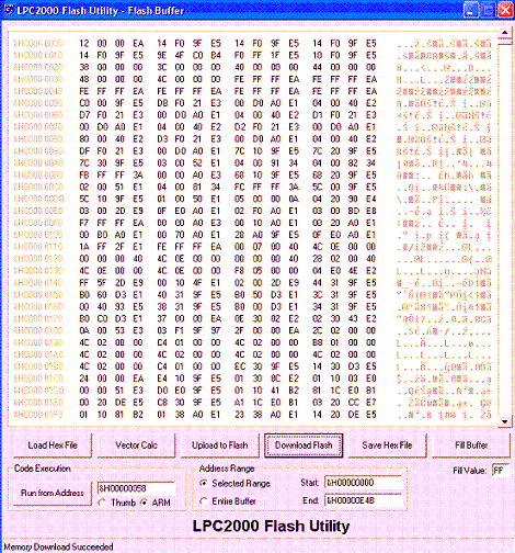
Press “load hex file” and select the hex file you need to upload to the microcontroller.
Press “Vector Calc” to generate a checksum, which will be located at the address 0x14. You will notice how this area updates after you press this button. Now you can save the hex file back to its location by pressing “Save Hex File.”
Now press “Download Flash” to download hex data from microcontroller.
In the main window, press “Compare flash” to compare flash contents and the original hex file.
Flash Utility allows SRAM buffer operations. You can download microcontroller RAM contents, modify and send them back to the microcontroller.
You can also run program code from the selected address location, fill the buffer with some values, and so on.
program for philips flash utility software