Regular ad hoc filters don’t guarantee optimal signal filtering as there are no criteria that evaluate filter characteristics. Usually, filter parameters are calculated empirically, and the best results do filtering. To avoid such a shortage, there are optimal filters used where some criteria optimize parameters. Optimal filtering’s main idea is to give bigger weight coefficients to signal spectra parts where signal noise has less power, and true signal spectral components have bigger power.
Let’s project a simple Butterworth filter used as a comparative filter to optimal Wiener DSP filter.
Butterworth filter transfer characteristics:

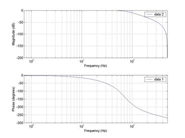
Where N indicates filter Tap number. I will skip the Butterworth filter description as the main idea is constructing an optimal Wiener filter. Butterworth filter characteristics are pretty plain:

The main disadvantage of the Butterworth filter is that signal is distorted on filter output. If you want minimal signal distortions it is better to use an optimal Wiener filter. Filter chart looks as follows:

As you can see, to make this filter functional wee need additional conditions like a signal model reference. Filter coefficients are calculated using MMSE. Root mean square error. Let’s see how it works.
Filter input is an ideal signal plus noise:

and filter output depends on filter weights of coefficients wk

Further, we need to optimize filter coefficients wk to meet minimal signal error e(n):

As we can see, minimal root mean square error depends on ideal signal model construction. In the frequency domain, optimal Wiener filter coefficients are calculated by using the Wiener – Hoph equation:

Where Sn·(w) – noise power spectral density;
Sd(w) – signal model power spectral density.

Where Rn·(m)- noise self correlation function.
Let’s see what results we get. First of all, we have made a Butterworth low-frequency filter. Signal sampling frequency was used – 1000Hz. We have made a couple of examples when filter tap numbers are 4 and 8 and cutoff frequencies are 30 and 70Hz:


It is tough to assemble good parameters for the Butterworth filter because there are no good criteria to value filter accuracy. So the following step is optimal filter construction.
First of all we need signal model reference:

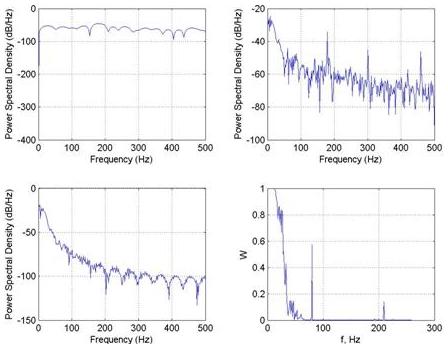
According to previous formulas we calculate filter coefficients depending on signal and signal model spectral densities:

When we have the Wiener-Hoph equation with all the required coefficients, we can filter the ECG signal. First of all, filtering is done in the frequency domain. Let’s calculate signal Fourier transformation, then filtering is nothing more than multiplying signal Fourier transformation by filter coefficients. Results are in the following picture:

Of course, you can filter signals in the time domain. For this, you have to make a reverse Fourier transformation of filter coefficients. If wee takes 30 filter coefficients we get:

Now we can compare filtered signals by using Butterworth and Wiener filters. One of the comparative methods can be the calculation of group delay. In the following results, we can see that using Butterworth filter group delay is biggest at 70Hz while Wiener filters resulting group delay oscillates around 0.

According to the results, it is tough to say which filtering method is better. Using tap 8 and 30Hz Butterworth filter gives more clear Q segment while using a Wiener filter, this part of the signal is hardly noticeable. Of course, the signal model is quite rough; this results in less precise filter coefficients.
Project files: mat1.mat and trm.mat files


Hi! Please tell me where can I find the files that you use in this program (mas1.mat, trm.mat). Thanks!
Attached files to the end of article.
How do you implement such a low frequency filter in real life?
i want a band pass filter at .5 to 3 Hz.
i have designed a butterworth fourth order filter for the same using matlab’s filter design toolbox. is it possible to make an active filter which works in this range?
or should i go for a real time DSP filter?
hello…can i get brief explanation about the matlab program given….like the functions used and process being done.brief explanation about each part…plz
hey..can i get the input signal also….ecg_hfn.dat…i want 2 try this prog but it shows error when i import some other signal…
hi,
iam working on ecg signal spectral estimation..
iam new to signal processing… i need to sample my signal 500hz.. after that i need to eliminate the frequencies above 35Hz and after that i need to apply fft for specturl estimation..
and one more dought is .. which filter is the best for ecg signal analysis… waiting for reply
my mail id is askanianji@gmail.com