This is continuing of thread AVR controlled signal generator. In earlier post 1 layer PCB prototype, I described a little about making this small project’s PCB. Now a few words about soldering and making the first test run.
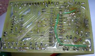
>This is my PCB board’s bottom. During soldering, I discovered one mistake – ISP headers pin MISO and MOSI were swapped. So I had to do some fixes (the green wire).

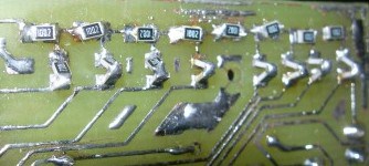
Another small problem I discovered was that I couldn’t find 20k SMD resistors for my R-2R leader. For this DAC R-2R leader, I need 10k and 20k resistors to make DAC work properly. So I decided to make “fun” with my Board and soldered 10k SMD resistors in series to gain 20k:

Looks good, isn’t it? At least this is working for me.
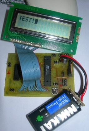
The LCD connector then soldered and connected 9V battery (voltage regulator LM7805 does its job to reduce it to 5V).

In this project, I connected LCD using 3 wires. I used this test program, and it worked.
I will have to adjust LCD routine properties to have better timings (delays) because now the code is inefficient and takes too much time to execute.
The next stage will be to connect the buttons needed. I think I will put all buttons on a separate PCB and fix it to the final box-like in Ultraviolet light source UV-80 for the PCB exposure project.


Hello. It is test.
I am here at a forum newcomer. Until I read and deal with the forum.
Let’s learn!
pleae sir….
i am bagio please sir, full avr signal generator PCB, schematic, .asm ,.hex. trims sir