A signal filter is an electrical equipment that attenuates the unwanted signal characteristic wave. Filters can be analog or digital.
An analog filter processes analog signals. They are mainly arranged with capacitors and resistors.
Digital signal filters process digital signals which are quantized. Digital filters are arranged with solid-state components to process the signals.
L’s start from analog filters.
An Analog filter is a circuit that filters unwanted frequencies. Filtering is done by choosing the circuit transfer function.
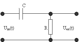
Simplest analog low pass filter:

The current in RC circuit can be calculated as follows:

Then if we think about digital filtering, then Uin(t) and Uex(t) we can change to xn=x(nT) and yn=y(nT). Then we can rewrite equation:

Then we get:
yn=a0xn+a1xn-1-b1yn-1,
Where
a0=1/(1+T/RC), a1=-1/(1+T/RC), b1=-1/(1+T/RC).
This equation now can be used to build digital filter.
The filter can be described using the response function. The response function of the analog filter is a reaction to step function while the digital filter response function is a response to a step function in samples:
u[n] = 1, if n>=0
u[n] = 0, otherwise
According to the method described in the previous article, we can calculate filter transfer function h(n);
Results are in following table:
| Filter | h at t/RC | ||||
| 0 | 0.5 | 1 | 1.5 | 2 | |
| Analog | 1 | 0.779 | 0.368 | 0.223 | 0.136 |
| Digital | |||||
| T=0.5RC | 0.667 | 0.444 | 0.296 | 0.198 | 0.132 |
| T=0.25RC | 0.8 | 0.512 | 0.328 | 0.21 | 0.134 |
| T=0.125RC | 0.889 | 0.555 | 0.346 | 0.216 | 0.135 |

From this chart, you can see if the time T between samples is smaller, then digital filter trends to analog filter characteristic. This means that you may choose digital filter error by varying sample steps.
Digital filters have some advantages over analog filters. For instance, in some circumstances, an analog filter can’t be valid while a digital can be valid.
Besides transfer function filter can be described using Laplace transform:
H(s)=y(s)/x(s).
And x transform:
H(z)=Y(z)/X(z).
Z transform can be done in following way:

Inverse Z transform:

I am not going too deep in it as there are tons of information about Z transform:
Using Z transform we can rewrite our filter equation in following form:

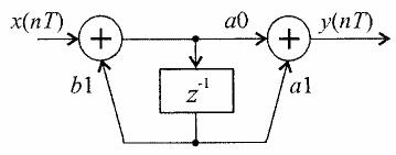
This is one Tap filter and its structure:

zÂ-1 means delay by on sample, T -one clock period. a0, a1, and b1 are filter coefficients (multipliers).
We can rewrite filter equation in other way:

Now its easy to write filter transfer function:
H(z)=(a0+a1z-1)/(1+b1z-1)
And filter frequency response:


