More and more design operations become automated. These changes give many benefits like effectiveness, minimal errors, and less routine operations to designers. Modern electronic equipment requires scrupulous planning as devices shrink to minimal sizes, operation power increases, and it fit its external design requirement. So designing is a very complex task where without smart CAD software would be almost impossible to do.
When designing a new electronic device, you have to deal with several necessary areas to make the device a reliable and attractive device. All of these areas usually are done on a particular CAD system. The most common CAD-based electronic specific task are:
- Mixed Analog-digital device modeling;
- Programmable Logic modeling and synthesis;
- HF circuits and electromagnetic modeling;
- Functional modeling;
- PCB Design;
- Thermal modeling;
- Chip topology modeling.
Each of these modeling and designing processes requires different skills and knowledge.
Let’s go through each to see their specifics and what CAD systems are used to automate related tasks.
Mixed Analog-digital device modeling
This is the most common task among electronic engineers. Today almost all Electronic CAD systems have circuit capture tools that enable circuits and model them. In most programs, circuit modeling is done via SPICE(Simulation Program with Integrated Circuit Emphasis). SPICE standard was created at Berkeley university in 1975. SPICE is a set of functions that allows the description of electronic devices and simulates them. So you can simulate electronic circuits with a computer without having a real prototype board. Using SPICE, you have flexibility and speed. Because it is possible to change parameters or change a circuit itself and simulate under different parameters changes and other circumstances, you can’t do many changes on a real board. Sometimes, you haven’t the ability to measure all characteristics. Few CAD software packages that include SPICE are:
Altium Protel DXP Design Explorer

Protel DXP Design Explorer is a professional tool that allows creating projects from beginning to end. Here you can create, simulate circuits, develop PCB. It also gives the ability to develop FPGA devices. Tool not recommended to hobbyists and beginners.
Cadence PSPICE A/D included into ORCAD package
ORCAD is also a very flexible tool-set that is loved in the academic environment because of its various simulation and analysis.
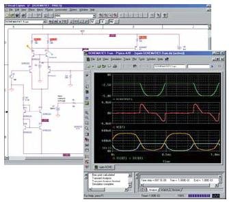
It is quite flexible and has, and many simulations result in analysis functions. It also has a valuable tool, PSPICE optimizer, that allows optimizing circuits according to various criteria.
Electronic Workbench
This is another powerful tool for circuit simulation developed by the National Instruments Workbench Group. The electronic Workbench Simulator environment is very intuitive and easy to use. It has many circuit analysis abilities like DC Transfer Function, Small Signal Analysis, Distortion Analysis, Noise Analysis, Sensitivity Analysis, Transient, Fourier analysis, and more. Electronic Workbench comes in a Multisim package, including a PSPICE simulator, PCB design tools, D breadboarding, etc.
Here are lots of more packages that simulate circuits like Proteus, which have the ability to simulate Microcontrollers or even open-source projects like Ngspice or Tclspice.
Programmable Logic modeling and synthesis
Programmable logic is more and more becoming a common part of any system. It has many benefits compared to microprocessor systems, likeability to parallel operations, to significantly increase performance. Especially in DSP systems. Programmable logic circuits are programmed in PLD, CPLD, FPGA chips. Usually, these logical functions are programmed using HDL languages like VHDL or Verilog. There are quite many packages to work with Programmable logic devices like:
- Altium program PeakFPGA;
- PLD module in Protel DXP;
- Cadence modules in ORCAD;
Programmable software is mostly accessible from chip manufacturers list of the FPGA design software you can find here.
HF and microwave circuits modeling
More complex tasks are when frequencies go UP. The main reason is that currents are flowing differently in inductor volume in high-frequency circuits, and there are noises very actual. To model Microwave circuits, there have to be Maxwell problems solved because SPICE modeling doesn’t work here. There are several Microwave studios available to work with HF circuits:
Microwave Office
Microwave Office combines linear and non-linear circuit analyses, design, multilayer electromagnetic modeling.
Ansoft HF modeling packages include various products like Hig-Frequency products(Ansoft Designer, HFSS, Nexxim), Signal Integrity products(DesignerSI, Q3D Extractor, SIwave, TPA), EM products(Maxwell 2D, Maxwell 3D, Simplorer, PEexpert, Rmexpert)
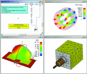
It solves full 3D volume problems by using the Finite element method to find a solution. Results are displayed graphically what makes it attractive.
Functional modeling
Functional modeling is high-level design modeling where you have to model systems at the object level without going too deep into the circuit level. As one suitable tool for this, I would mention Matlab Simulink. Matlab is a universal package as it is a mathematical modeling tool, but it has many standard libraries with practically unlimited abilities.
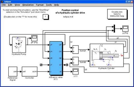
Matlab can simulate practically any object, including mechanical, electrical, financial, neural, etc. This is why it is a top-rated tool among most engineers. If not present, you can create any model in Matlab.
PCB design
PCB design is one of the last steps in the project. Its purpose to get a working prototype that was simulated previously. This part has a big competition which tool is better. Maybe this is why so many tools are available now like: Altium P-CAD, Altium PROTEL, Cadence ORCAD, EAGLE CAD, Mentor Graphics Expedition PCD, and more. These packages compete, which is better in auto placing, auto-routing, signal integrity. Bigger packages like OrCAD and Protel are dealing with footprint databases. Protel can work as a client-server architecture that has a centralized element base.
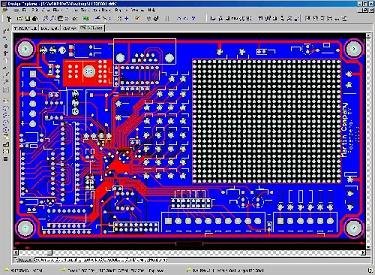
There are special routing module SPECTRA used in higher integrity circuits, which enables customization of tracing according to various parameters. But again, there is no algorithm created yet that can be trusted. The last word is engineers. Usually, he has to fine-tune PCB before it can be produced.
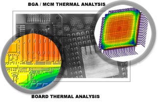
PCB thermal analysis
Thermal analysis of PCB is done when serial production is going to be done. This is a complex task as it requires many parameters on how different chips dissipate power, what materials are used, etc. There are several CAD packages like BETAsoft, Sauna(Thermal Solutions).
Chip topology modeling
This is a little different modeling area as it takes IC modeling itself. IC manufacturers use expensive and specialized software, which costs big money. Integral chips can contain hundreds to millions of elements in one crystal, so task complexity is huge. Companies like Intel, AMD spend billions of dollars in equipment to make new processors.
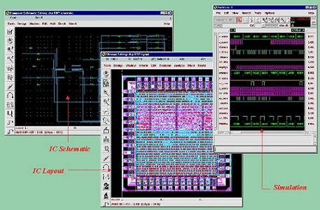
CADENCE produces packages for designing IC’s using various technologies. Software is more oriented to digital IC design and simulation.
Source: technologijos.lt


Hi,
I really like your website. It makes me want to know more about things you explain.
Do you know if some tools that combine Analog simulations and digital simulations exist? I would like to simulate an analog circuit interacting with an FPGA through ADCs and DACs.
Thanks