After the ARM mini-board for LPC2148 is created, it’s time to develop a development board. I want to make the board as universal as possible.
So I decided to put I2C, SPI, COM, and JTAG on board. I decided to use an external voltage adapter as there are needed 5V and 3.3V DC sources. For my experiments, I can use those voltages straight from a PC source. 5V there is used to supply MAX232IC. I decided to use it instead of MAX3232 because it is easier to get them in the market. Of course, I left the ability to use and MAX3232 by changing the jumper. All other free pins I made accessible by adding pinheads inboard.
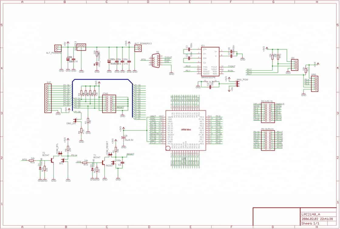
I made 100x100mm double sided PCB
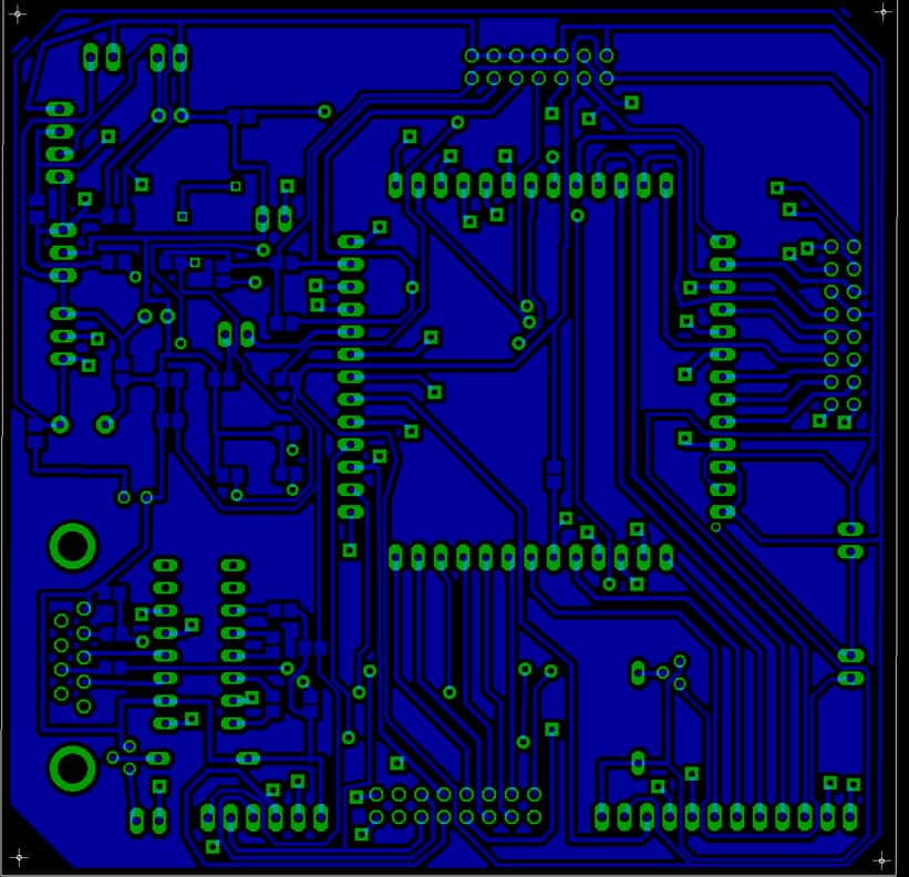
PCB Bottom image
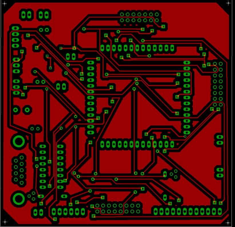
PCB top image (when printing – use mirror function)
And real world images.
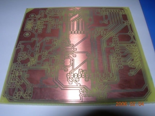
PCB Bottom
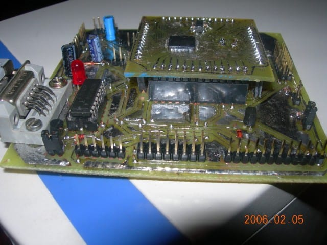
Completed soldered board with ARM mini board on top.
And, of course, I put Eagle3D traced board images. Best regards to Matthias Weißer from www.matwei.de did a great job doing such work.
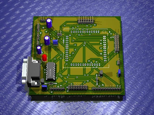
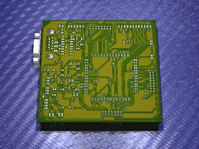
The first read/write tests I run with Philips Flash Utility were successful. Next time I’ll post a few articles on how to get this board running by writing C code, compiling, and flashing the ARM7 LPC2148.
Download Eagle files here: lpc2148baseeagle.zip


ok
well done great job
great blog
i will visit it daily.
hope some new things will happen,
i might build your board. i am a student in germany
strasset@fh-trier.de
not a nice web page on our school, but´s time to do that job,
sinc
tobi
hello
I want the programme for LCD in C written for LPC2148.
Can u mail me the program. I will make the changes.
mail me– mahawar_ashish21@rediffmail.com
Publishing LCD routines is in my near plans.
Very good job! What are the sections on the pcb with large copper areas called and how do you do them in eagle ( are they gnd. plane) ?
what are the isp / jtag tools for this thing and are they universal for all /most ARMs?
About copper areas – then can be created by drawing polygon and then by pressing Ratsnest. You can make it GND or isolated. In my example areas are isolated.
In most cases ARM is programmed with built in Bootloader via RS232. Or you can use universal MACRAIGOR WIGGLER COMPATIBLE Jtag adapter, or any other.
Are they used to reduce emi since they’re isolated?
Are any or all of the programming s.ware you mentioned free and can you recommend a good
PRACTICAL book about the ARMs?
thanks
The only good book for starting with ARM I can recommend is Insider Guide
http://www.cecs.csulb.edu/~brewer/347/lpc-ARM-book_srn.pdf
Would usbprog work with most ARMs and do you know if it is a reliable programmer?
Do you have jtag and if so, which hardware ?
Thank you for the ARM book refral, it’a very good.
I haven’t build it yet, but I am going to build one soon. Adapter is Olimex ARM JTAG clone which is easy to build and works with WinARM tools (ocdremote and gdb/Insight-gdb). Circuit is here:
JTAG wiggler clone
Hi
I am new to ARM and am planning to make my own development board for LPC2148. Can I go ahead with your design? I just want to test ARM’s powers, and am plannning to program it from RS232.
You are welcome to do it board fits your needs. As far as I have tested this one – it worked OK.
Why did you leave pour copper isolated? This is never a good idea. It can help noise to capacitive coupling to other traces, although you have no problems in good function. Better to join pour copper to ground and never leave islands of pour copper (i mean don’t join in 1 only place the pour, stitch with vias to ground in more than 1 place to avoid islands).
On other hand, i wanted to thanks your blog, because i’m doing my first arm7 board and i’m looking your schematic to base my board on yours.
This board isn’t the best example. It works for me as simple dev board. But you are welcome to look at schematics and trace your own PCB. I Agree that leaving copper islands is bad idea – better to ground them or not to put at all.
Thanks for your post,
please send me the eagle schematics and layout. i can’t find the download in your post.
Could you please send me the eagle schematics and layout of your lpc2148 base development board.
Much Obliged,
Pixel
Could you please send me the eagle schematics and layout of your lpc2148 base development board to maheshkuruganti@gmail.com
Thank You,
Mahesh K
Sorry somehow it wasn’t attached. I have added files at the end of the post. I believe you can improve PCB routing.
Its good one,thank you.
Could you please send me the eagle schematics and layout of your lpc2148 base development board to
nimbalkar.abhijit007@gmail.com