1-Wire protocol simple and easy
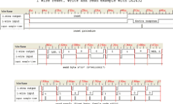
Dallas Semiconductor, owned by Maxim, developed the 1-Wire communication protocol. This protocol allows the communication of multiple chips to one host with minimal pin count. The protocol is called 1-Wire because it uses 1 wire to transfer data. The 1-Wire architecture uses a pull-up resistor to pull the data line’s voltage at the master side. 1-Wire protocol uses CMOS/TTL logic and operates at a supply voltage range of 2.8 to 6V. Master and slave can be receivers and transmitters, but only one direction at a time. LSB goes first always. Time slots transfer data in the 1-wire network. For instance, to write logic “1”, the master pulls the bus low for 15us or less. To write logic “0,” the master pulls buss low for at least 60us. The system clock is not required as each part is self-clocked and synchronized by the falling edge of the master.

Continue reading

How to make 5V from 1.5V

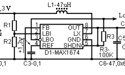
In many cases can be very handy to be able to convert 1.5V to 5V. Then you can power a microcontroller or an LED from a single AA or AAA battery. It is simple to do this as there are special IC’s as MAXIM MAX1674 or MAX7176. This is a step-up DC-DC converter that can convert voltages from 0.7V to any in the range from 2V to 5.5V. MAX1676 already has preset pins for 3.3V and 5V, making easier integration in 3.3 and 5V circuits. IC can dissipate up to 444mW. Bellow is a circuit that converts 1.5V to 5V. We need to get the maximum output of the current 300mA; then, we need to put some effort. Because output power is 5V·0.3A=1.5W, let’s say efficiency is 100%, then the power drawn from the battery will be 1.5W too. At 1.5V voltage, this will be 1A current. Not all batteries can drive such currents. Another important part is an inductor. For this wee need inductor with high current saturation, which usually leads to an increase in size.

Continue reading

Ultrasound transducers for measuring distance

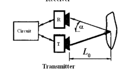
Ultrasounds transducers for measuring distances are commonly used in robotics, automotive parking sonars. Ultrasound distance measuring is non -contact measuring method – radiation and reception of ultrasound waves. Ultrasound waves are mechanical acoustic waves with frequencies more than 20kHz. Normally humans cannot hear frequencies above 20kHz, while some animals can. For instance, bats use ultrasound location of objects. Dolphins communicate with each other using ultrasound signals. Ultrasound interacts with a hard body, and part of incoming wave energy is reflected; in other words – it is backscattered. So direct wave towards an object is backscattered widely – up to 180°. If the object is moving – the received frequency differs because of the Doppler effect. Let’s say simple example – parking sonar. Distance to object can be calculated very simply by the formula:

Continue reading

Avoid noises in mixed signal design

Today most of all embedded systems consist of two-part circuitry – digital and analog. The Digital part is usually the controller, its timing circuit, and other input-output devices. Frequently there is an analog part on the same board like ADC, OP amplifiers, sensors, and other analog circuitry. Such designs are called mixed-signal designs. Where digital and analog parts meet – the grounding problems start. The fact is that each conductor has its own impedance, so any current flowing results in voltage drops. Ground wires and planes aren’t exceptions. Digital and analog grounds can generate significant electromagnetic radiation that adds noises to signals we need. So the overall system quality drops because o poor design. In a good design, the analog ground plane and the digital ground plane should be separated. With multilayer PCB, this can be done very easily. Another issue is that digital signal traces shouldn’t cross analog ground, and analog signal wires shouldn’t cross the digital ground plane area. Of course, try to avoid aligning digital and analog wires as they can catch each other radiated noise.

Continue reading

LPC2000 Flash memory and its programming

All-flash memory of LPC2000series microcontrollers is arranged as two interleaved banks. But user sees it as one memory space. All-flash memory appears to the user as series of 8K sectors. These sectors can be written and erased individually. There are several methods of how flash memory of ARM can be programmed. One and easiest way is to use a built-in bootloader. The code is downloaded by bootloader via USART0 to RAM, and then it is programmed to Flash. There is a tool for this – Philips ISP Utility that works under Windows environment. Another method is to use JTAG to program flash memory. This method is usually used from debugging environment. JTAG is faster than ISP – reaches up to 400kB/s. The third method is the ability to reprogram Flash memory sectors using application commands that are on-chip. This feature is handy for updating code in a given section. This is so-called Field Updating.

Continue reading

Eagle CAD PCB footprints for audio processors TDA7313 and TDA7315

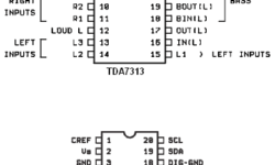
TDA7313 and TDA7315 are digital controlled audio processors used in applications where digital control of audio is needed. TDA7313 and TDA7315 are pretty the same just TDA7313 is more complex by having 3 stereo input channels and two outputs (front and rare). Both chips have volume control (step=1.25dB), tone (bass and treble) balance, independent faders for each output processor. Also, there is loudness functionality. TDA7313 and TDA7315 have low distortion and low noise, making them ideal for quality audio applications for car audio and Hi-FI systems. MCU can control both chips via the I2C(TWI) protocol. This makes it easy to interface microcontrollers with additional features like LCD, buttons. Or control directly from PC using RS232 or another interface. Both chips can be found in DIP or SO packages. Here are Eagle libraries of both digital audio processors that I have made. tda7315.zip(2kB) tda7313.zip(2kB) I have intent to make a control board with TDA7315 with LCD and button control using an Atmega8 microcontroller.

Continue reading

Calculating of electrical heating elements

Electrical heating elements are often used for teapots, irons, electric ovens, soldering irons, etc. When projecting designs with electric heating elements, you need to do some calculations that may seem difficult at first glance. But when looking more deeply, this becomes a simple task. We know that electric heating is a result of the current flow in wire with some resistance. The resulting heat is work done by electric current. Work A(J) can be calculated by the formula:

Continue reading

Calculating wire diameter for maximum current

When selecting wire diameter, we usually look for cross-reference tables to find the recommended wire diameter for the maximum current drive. But sometimes maybe more useful to calculate by formula than look into the tables. This way, you can have more accurate results. There is nothing new, just simple physics. Wire resistance (Ω)is calculated as follows:

Continue reading