As I earlier was writing about my homemade ARM7-Base development board for LPC2148

It is time to write few words on how to use LPC2000 flash ISP utility.
LPC2000 flash utility is a software that is used to program LPC2000 series ARM microcontrollers:
LPC2101, LPC2102, LPC2103, LPC2104, LPC2106, LPC2106, LPC2114, LPC2114, LPC2119, LPC2124, LPC2129, LPC2131, LPC2132, LPC2134, LPC2136, LPC2138, LPC2141, LPC2142, LPC2144, LPC2146, LPC2148, LPC2194.
Programming is done through the serial port. As you probably know, the LPC2000 series microcontrollers come with a boot-loader built-in. This bootloader provides an ISP interface for programming Flash or RAMs and other operations like erasing. The bootloader is located in the upper 8kB flash memory.
The bootloader has an algorithm that detects incoming ISP connection, detects baud rate automatically.
When starting ISP after reset, P0.14 has to be pulled down what means that microcontroller is ready to accept ISP commands. Otherwise, keep the P0.14 pin pulled high to avoid unintended ISP entry.
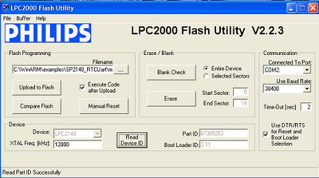
Lets take a look at main screen of LPC2000 flash utility:

The program has a very intuitive screen. The first thing you have to do is power up your target board and connect the serial cable to your computer. Then in a screen, select COM port number and baud rate. If you use automatic ISP entry mode, then check DTR/RTS checkbox – in a board, DTR and RTS lines have to control the P0.14 pin and RESET pin. Otherwise, use manual entry mode.
If ‘execute code after upload’ is selected, then an extra reset pulse is sent to reset the microcontroller after programming completes.
Next step, you have to enter crystal frequency in kilohertz. After this, press ‘Read Device ID’ to make sure that the device is detected correctly. Part ID and boot-loader ID is detected. If successful, you can now start programming your microcontroller.
Open hex file and press upload to flash’ to send code to the microcontroller. ‘Compare flash’ button is used to compare original hex file contents with uploaded. This operation is possible if the checksum is part of the hex file already.
Checksum can be generated as follows:
Open buffer menu and select ‘Flash buffer operations’:

Press ‘load hex file’ and select the hex file you need to upload to the microcontroller.
Press ‘Vector Calc’ to generate a checksum, which will be located at the address 0x14. You will notice how this area updates after you press this button. Now you can save the hex file back to its location by pressing ‘Save Hex File.’
Now press ‘Download Flash’ to download hex data fro microcontroller.
In the main window, press ‘Compare flash’ to compare flash contents and the original hex file.
There is also SRAM buffer operations available – pretty the same as a flash buffer. You can download microcontroller RAM contents, modify and send them back to the microcontroller.
You can also run program code from the selected address location, fill the buffer with some values, and so on.
This utility does not support other ARM microcontrollers like LPC2220/2210/2290 as these microcontrollers don’t have inner flash memory. But utility can be used because it can send ISP still can access SRAM memory, read device ID. Just ignore the Error message and go ahead.


Hi Rakesh universal programmer is a programmer which can burn all types of MCU’s therefore you just have to change the configuration/fuse bit of atmega8 jast spien No need to perchase since it is quite costly you just have to look after some shop or training institute for the programmer.
we need total details for isp based program for lpc2148
hi. why you have used the baud rate to be 38400 instead of 9600. and why you have ticked execute code after upload.
As far as I remember, baud rate could be changed to higher values for faster upload rate. second option does what it says – starts program after upload. You can untick it…