
LDR (Light Dependent Resistor) is a simple, cheap electronic device. This is a resistor in which resistance varies depending on light intensity. You’ve probably seen typical LDR in some projects where light intensity must be considered. They can activate light switches and alarms, adjust display brightness, and more.
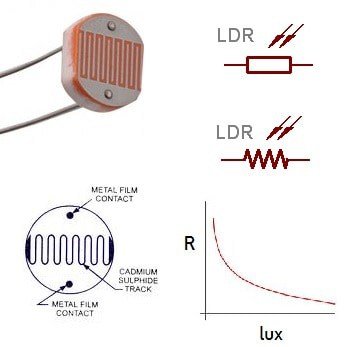
Light-dependent resistors can be of different types. They vary in light-sensitive material used. Visible spectrum LDR is made using Cadmium Sulphide (CdS) or Cadmium Selenide (CdSe). This material is sensitive to the wavelength range from 400 – 850nm. For the near-infrared spectrum (1μm – 3μm), there are PbS or PbSe materials used. For the deeper infrared range (3μm – 1000μm), there are InSb and InAs.
Another important parameter of LDR is resistance in dark and light. Usually, at night, resistance is in the mega-ohms range. While in light, resistance is a few kilo-ohms.
LDRs are pretty inertial. It takes tens to hundreds of ms to settle on sudden light level change. So they aren’t the right choice for use as signal receivers – better go with semiconductors. LDRs have their niche, and they do a good job there.
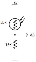
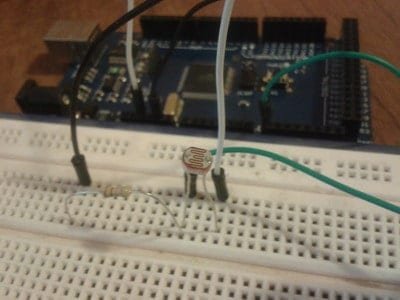
Let’s build a simple project on the Arduino board. We will try LDR resistance when in dark and room light. First, we must construct a voltage divider using a 10k resistor and LDR.
This circuit is straightforward to understand. When there is no light, LDR resistance is ~5MΩ, so directly speaking, the analog pin’s voltage is very close to 0V. And when there is light present – the resistance is a couple of kΩ or even less for very intense light. Then voltage on the test pin gets closer to 5V. This is how the majority of LDR-based circuits work. Let’s connect this divider to Arduino Mega1280 analog pin A8 and do some measurements.
Let’s write a simple program to output analog readings and calculate the approximate resistance value to the serial terminal.
int VCC = 5;
int R = 10000;
int ADCmax = 1023;
void setup() {
  Serial.begin(9600);
}
void loop() {
  // read the input on analog pin 8:
  int sensorValue = analogRead(A8);
  // print out the value:
  Serial.print("ADC Value: ");
  Serial.print(sensorValue);
  //calculate voltage on A8
  float voltageDrop = (float)VCC/1023*sensorValue;
  Serial.print("; Voltage Drop: ");
  Serial.print(voltageDrop);
  Serial.print("V; ");
  //calculate LDR resistance
  float LDR = R/voltageDrop*(((float)VCC-voltageDrop)/1000);
  Serial.print("LDR: ");
  Serial.print(LDR);
  Serial.println("k");
  // delay in between reads
  delay(2000);
}
This small program may be handy to see what typical LDR values you get on different ambient light:

As you can see, when the room light is ON, we get an ADC value of about 650, and the calculated voltage drop is around 3.15V. Having this data, we get ~5.8kΩ resistance. When I cover LDR with my hand, I get ADC of about 50, which is approximately a 0.25V drop and a calculated resistance of ~190kΩ. With a lighter close to LDR, I get less than 1kΩ. With such data, you can build intelligent systems with several threshold voltage drops if needed.
We can build another quick project with motor control with these experimental values. Let us attach the servo motor to Arduino PWM pin 10. Let us take that 0º angle will match the 0V drop. 180º will be 5V. Then we can move the servo shaft according to the ambient light on LDR. Let’s make rotation resolution 1º. So 1º step will be 5/180 = 0.027V. Now we can write our program:
#include <Servo.h>
//create servo object
Servo servo1;
int VCC = 5;
int R = 10000;
int ADCmax = 1023;
float degstep= (float)VCC/180;
void setup() {
  Serial.begin(9600);
  //attach servo1 to pin 10
  servo1.attach(10);
}
void loop() {
  // read the input on analog pin 8:
  int sensorValue = analogRead(A5);
  // print out the value:
  Serial.print("ADC Value: ");
  Serial.print(sensorValue);
  //calculate voltage on A8
  float voltageDrop = (float)VCC/1023*sensorValue;
  Serial.print("; Voltage Drop: ");
  Serial.print(voltageDrop);
  Serial.print("V; ");
  //calculate LDR resistance
  float LDR = R/voltageDrop*(((float)VCC-voltageDrop)/1000);
  Serial.print("LDR: ");
  Serial.print(LDR);
  Serial.print("k; ");
  // delay in between reads
  int servoPos = (int)(voltageDrop/degstep);
  servo1.write(servoPos);
  Serial.print("servo: ");
  Serial.println(servoPos);
  delay(1000);
}
And here are the serial terminal results:

As you can see, working with light-dependent resistors is easy. You can put a straightforward automation system with the servo motor in an hour. I hope you enjoyed this walkthrough, and now you can check darmowe maszyny hot spot for relaxation.