
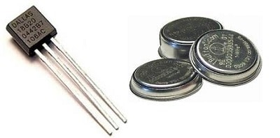
1-wire devices are commonly used in many applications. You probably are familiar with the famous DS18B20 digital temperature sensor in the TO92 package. They can be powered and interfaced using the same single data line plus the ground return, of course. 1-wire originally was designed by Dallas Semiconductors Corp., which is also a major provider of 1-wire devices like temperature sensors, timers, real-time clocks, memory, and the well-known iButton.
1-wire interface is a bidirectional, half-duplex slow serial communication standard. It doesn’t use any clock signal. When talking of speed, the standard data rate is 15.4kbps. But there is possible to overdrive 1-wire communication to up to 125kbps.
1-wire signaling is based on one master and multiple slaves configuration. Each slave has a unique address stored on-chip ROM. Master can recognize each slave by reading this address without any conflicts. The number of slaves may reach 100. But practically polling such a number of slave devices would take a long time. This should be taken into account when designing responsive systems.
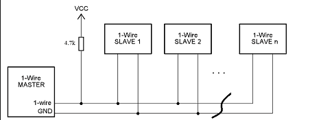
Master and slave devices use an open-collector (open-drain) connection to the bus line.

So there is a pull-up resistor needed. Normally 4.7k resistor is used to pull the lineup.
Powering modes of 1-wire devices
Most 1-wire devices can be powered using two methods: parasitic and conventional. The parasitic mode is what enables signaling and powering devices via the same data line. In this mode chips, the VCC pin must be connected to the ground, while the data line is pulled high through a 4.7k resistor. During high signal state 1-wire devices, an internal 800pF capacitor is charged, which ensures enough power during a low state of the line. Using parasitic more, it is important to meet timing and power specifications to ensure enough power for proper operation. In some cases, a helping hard pull-up may be used to provide enough power during data line inactivity (for instance, during temperature conversion):

Since parasitic powering may not always be a reliable way of powering, there is a conventional way by simply powering the device with an external power supply. This way, instead of two wires, you will need to trace three:
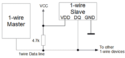
By powering devices with an external power supply, you can ensure safe operation even in higher temperature environments. Also, you don’t need to include a hard pull-up.
Communicating to 1-wire devices
Usually, you won’t find a 1-wire interface in microcontrollers or PC. To communicate, you need to use software-based bit-bang signaling or insert a 1-wire line driver that connects with one available interface like SPI or I2C. In most cases, when the microcontroller is used, 1-wire devices are interfaced directly to MCU pin(s). You can already find ready libraries for fast implementation or write your own. Let’s see how 1-wire signaling works. Once we clear things out, it will be easy to write your own routines. To send binary numbers 1s or 0s, there are time slots used. Depending on how long the line is pulled, low is recognized whether it is 0 or 1. When the bus is released from low in 15us, the short time slot is considered logical 1. At the same time, long slots at least 60us is 0. In overdrive mode, time slot durations are approximately 10 times shorter.
Communication is always started by the master, which resets the data line with a long pull-down (at least 480us). After master releases data line allowing pull-up resistor to pull the data line high. After a short time (up to 60us), slave devices pull the line to signal a presence signal. This pull lasts a bit shorter than the master reset (up to 240us). After the slave releases the data line, the master starts communication.

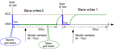
Master sends bits 0 and 1 by writing 60us time slots:
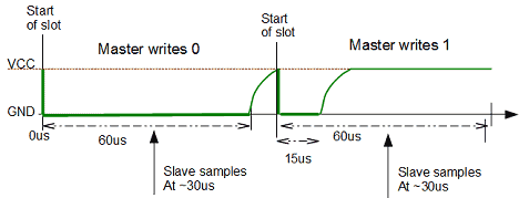
When the master is performing data write, it writs bits in 60us time slots. To write 0, it must pull the data line low during all 60us time slots. Slave then detects low during sampling and reads 0. When master writing 1, it has to pull low for about 15us but not more and then release the line. Pull up resistor pulls up the line, and slave during sampling detects high level and reads 1.
Master reading time slots:
During a master read operation, things get a little bit trickier, but not much. First of all, the master still controls read operation by pulling the line low during reading time slots. But this pull should be short (~1us) and then release the line. If the slave sends 0, it keeps the line pulled for the rest of the time slot. Master should sample the data line after 15us to 60us. If the master gets a low signal, then it must read 0. And again, during logical 1 read, the master pulls line for 1us and then releases. If after release, the slave doesn’t keep line pulled, pull-up resistor pulls data line up. Master should initiate sampling after like 15us to 60us. If it reads line high, it must read 1.
Normally delay between time slots should be about 1us for normal recovery.
The 1-wire transaction consists of three parts. Otherwise, it wouldn’t work.
- A 1-wire line reset;
- ROM command sequence;
- Function command sequence.
We already discussed the line reset. It gives a start to new signaling. ROM command enables to address slave devices. There are several ROM commands with various purposes. It would help if you looked in the device datasheet for those. But few of them are common, like Search ROM (F0h), where the master identifies all slave devices connected to the 1-wire data line. Each slave is equipped with a unique 64-bit address. So master during ROM search cycles through all slaves reads and stores all 64-bit addresses. Each cycle starts with initialization (line reset). If a single slave is connected, the master can use Read ROM (33h) command. When the master has all ROM codes next time, it can address the slave by sending Match ROM (55h) command.
The third part of communication is the Command sequence. This is where the master sends specific commands to slave(s) like start conversion if temperature sensors are used, read temperature value from the scratchpad memory, and so on.
Hi! Thanks for the info with great details! We can offer good quanlity iButton keys and iButton probes with reasonable price. Take a look at our website: iButton.CC for more info. Feel free to contact us in any time.
Hello, How many meter distance can have the last slave from the master without creating problem?