Serial Peripheral Interface is a simple interface that enables communicating microcontroller and peripheral chips or intercommunicating between two or more microcontrollers. Serial Peripheral Interface Bus, sometimes called four-wire interface, may be used to interface such chips or devices like LCD, sensors, memories, ADC, RTC. The range of usage is huge.
SPI Bus uses the synchronous protocol, where transmitting and receiving is guided by a clock signal generated by the master microcontroller. SPI interface allows connecting several SPI devices while master selects each of them with CS (Chip Select) signal – (Underline means that active is LOW).
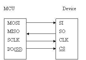
SPI bus consists of four signal wires:
- Master Out Slave In (MOSI),
- Master In Slave Out (MISO),
- Serial Clock (SCLK or SCK)
- Chip Select (CS) for the peripheral.
Some microcontrollers have a dedicated chip select for SPI interfacing called Slave Select (SS).
The master generates a MOSI signal – the recipient is Slave. MOSI may also be labeled as SI or SDI.
Slaves generate MISO signals. In some chips, you might find labels SO or SDO.
SCLK or SCK are generated by master to synchronize data transfers.
CS (SS) signal is also generated by master to select slave chip or device.

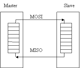
Data transfer is organized by using the Shift register in both: master and slave. While master shifts register value out through MOSI line, then slave shifts data into its shift register. If there is full-duplex used, then send and receive is performed at the same time:

There also are multiple byte stream modes available with the SPI bus interface. In this mode, the master can shift bytes continuously. Using this type of transfer slave select (SS) must remain low until all stream process continues. For example, you can write to memory by sending address bytes and then data in the same stream operation. In this way, kilobytes or more can be sent using multiple byte transfer mode.
Daisy-chained mode
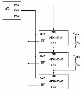
Some chips have the ability when you can connect multiple SPI devices in series, and data can be transferred to all devices through others. For instance, if you connect three devices to the microcontroller in series MCU-A-B-C, then MCU will have to send three bytes of information. The first byte goes to the C device, the second to B, and the third byte to A:

Daisy-chain won’t work with devices that support or require multiple bytes operation (memory chips).
For instance, AD8403 – 4-Channel Digital Potentiometer can be connected to a daisy-chain circuit:

Depending on Clock (SKC) polarity, there may be four operation modes of SPI:
- Low clock polarity – when the clock is low in idle and toggles in high;
- High clock polarity – when the clock is high in idle and toggles in the low stage;
- Clock phase zero – MOSI and MISO outputs are valid on the rising edge of the clock signal (from low to high);
- Clock phase one – MOSI and MISO outputs are valid on the falling edge of SCK signal (high to low)


I still not understanding, can you give me some information about SPI method ?
please help me.ASAP.
Adi
s3prayer@yahoo.co.uk
Very Nice Basic Concept regarding SPI
hi guys..
somebody plz help me about spi connection circuit between ATmega 16L and ps2 joystick..