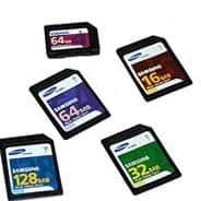
Multimedia cards are popular around us. There are well known Compact Flash, CD, MMC Memory Stick. Usually, when you make a new design with external memory, you consider EEPROM or Flash ICs with some capacities with up to a few Mb. But why limit yourself? Because in some cases, it is smarter to add a multimedia card socket and use any capacity (even a few Gb) multimedia cards in your projects. Using removable storage cards you get few advantages:
- You can share data from your card with any device that has a reader;
- You can have any size of storage memory;
- Easier to get one than specific IC;
- Cost-effective;

I really like Using multimedia cards because you can get huge amounts of storage of price small EEPROM or Flash IC. They are cheap because of mass production. They are available everywhere: digital cameras, Mobile phones, personal players, etc. Another advantage is that you can store data in a format that the PC understands. This way, it is easy to collect data for later analysis using PC software.
MMC and SD cards
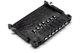
Multimedia cards(MMC) and SD-Media cards are compatible. Connectors are really cheap and easy to solder:

Below is an example of how to connect an MMC card to a 5V microcontroller using resistor dividers:

As you see MMC card communicates in SPI mode. SPI is a serial communication protocol similar to I2C but in many ways simpler. Many microcontrollers like the AVR family have built-in hardware SPI interface and can run in high data rates up to 100 times faster than I2C.
Interfacing an MMC card isn’t difficult just remember that MMC cards can be powered from 1.6V to 3.6. The picture above is an example of connecting to a 5V system with voltage dividers.
How do MMC cards work?
MMC cards are not only a Flash memory block, but it also has a small controller inside that is responsible for initialization, identification, and control. In SPI mode, You have to send commands to set up the card. Commands are typically five bytes – one-byte command and four bytes of parameter and optional check byte. Check bytes are not used if they are not enabled. Check bytes are to make sure that communications go without corruption.

Most of the commands return a response message which has to be clocked out from a card by sending a 0xFF. See details in specifications. What actions must be taken to start working with MMC:
- When the card is powered up, send a Reset Card command;
- Then send Initialise Card command, which takes some time;
- After Initialization is complete, you must retrieve card identification (16 bytes). Identification contains manufacturer info, card type, amount of memory in the card.
- Then read-write the card information.
Read and write commands use a 32-bit address parameter that allows addressing up to 4GB of memory. Reading can be done from any address, and you can read bytes by writing 0XFF bytes to latch out further data. Writing takes more effort because the memory in the cards is organized in 512-byte groups called sectors. So when writing sectors, the card erases it firstly and then writes data. This is tricky if you want to update a single byte. Usually, you would need additional 512 bytes of ram to read the whole sector, update it and then write. To make things easier, a command allows to set read and write buffer block size. If the block size is set to 512, then the read/write command starts from 0 or 512, or 1024 …
There are more commands like protection, multi-block write that is documented in specifications.


Thanks for great information, Really I was looking for this info ….
I want to ask if there is a sample application demonstrating the use of this technique with some microcontroller like the AVR
How to drive SD cards look at this source: http://www.ulrichradig.de/index.html .
I didn’t have a chance to try by myself yet.