
As you may know, ST also produces its own debugger/programmer called ST-Link. It supports JTAG and SWD interfaces. You can purchase an ST-Link USB adapter, but there is a better option if you are into STM32 microcontrollers and probably own one of the ST32 Discovery boards. Since I have STM32VLDiscovery nearby, this is how to program another STM32F103RBT6 board using only four wires.
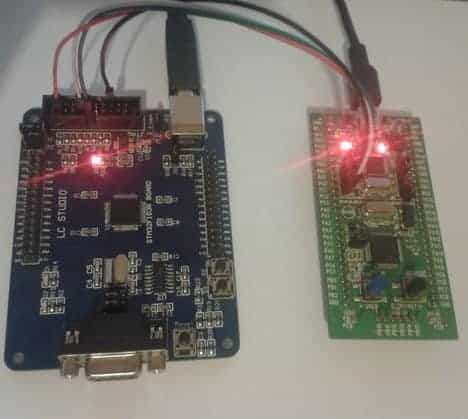
On the discovery board, locate CN3 jumpers and disconnect them as they connect the discovery board to a debugger.
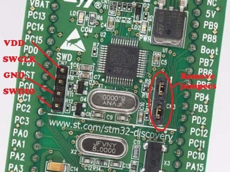
Then locate CN2 pins and connect them to target boards JTAG connector as follows:

- VDD (pin 1) to JTAG VCC (pin 1)
- SWCLK (pin 2) to JTCK (pin 9)
- SWDIO (pin 4) to JTMS (pin 7)
- GND (pin 3) to GND (pin 4)
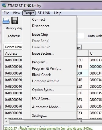
Power both boards and open ST-Link utility. You can see that the Medium Density board has been detected.

Now you can load the binary file, and program microcontrollers Flash memory. Using the Target menu, you can perform additional operations similar to J-Flash.
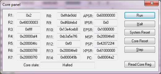
An exciting feature of ST-Link is the MCU panel. You can do various things like Run code, halt, step, reset, core reset, and read core registers. You can treat this panel as a quick debugger
You will find a great tutorial in the user manual in ST-Link install location on your PC.
A couple more flashing methods: embedded bootloader and Using J-Link JTAG adapter