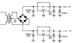
Switching step-up and step-down regulators

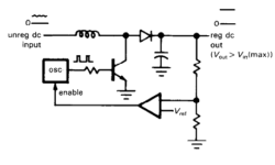
All regular voltage regulators (like 7805) have several disadvantages like output voltage is always lower than input, and some power is dissipated in the control element. Dissipated power is approximately equal to I(Vin-Vout). There is another way to generate a regulated voltage. The method is different from the previous one. A transistor operates as a saturated switch in a switching regulator, which periodically applies the full unregulated voltage across an inductor in short intervals. During each pulse, inductor current builds up, storing energy on its magnetic field: Inductor also smooths the output voltage. Feedback circuit with comparator compares the output voltage with reference and this way changes oscillators pulse width or frequency.

Continue reading

Dual polarity power supply source

Most op-amp circuits run from the symmetrical bipolar supply source, let’s say ±15V. The simplest way to generate symmetrical split supplies is to use a pair of 3 terminal voltage regulators. For instance, let’s take two voltage regulators: 7815 and 7915. If you need an adjustable variant of dual polarity regulated voltage source, you can use 317 and 337 adjustable regulators, where you can trim voltage with a voltage divider, which consists of two higher accuracy resistors:

Continue reading

What are electrical switches principles and switching problems?

Switches are an important part of electronic systems. It is one of the most frequently used human interaction with electronic devices methods. But switches are the mechanical components that are a vital part of any equipment. Electrical switches Electrical switches are as old as electricity. The function is always the same – it makes or breaks current in a circuit. In early 19th switches were used for DC circuits, while later for AC and then they serves for switching wide spectra signals starting from audio and ending with digital. Well, switches have changed compared to those before 100 years, but the principle is the same old as the electric itself. When the switch connects the circuit path, it has a resistance of mOhm, and when the current path is broken, resistance is high MOhms and higher. This resistance and maximum voltage that can be applied to insulation is often a major important and vital feature that leads to switching stability.

Continue reading

Overview of noises in electronic systems

AVR DDS noise signal

There are several sources of noise in electronic systems. Noises are unwanted signals polluting random or not signals that reduce overall signal quality. Thermal Johnson/Nyquist noise Two scientists, Johnson, discovered this noise who did the experiments and Nyquist, who developed the formula. Thermal noise is present at all frequencies (has a constant power density at all spectra) and is called white noise. This noise can only be reduced by reducing the temperature, resistance, and bandwidth. Let’s see the Noise voltage RMSformula:

Continue reading

Long range directional microphones-myth and reality

There are a lot of myths about directed long-range microphones. You can hear that they can reach distances of 100, 200, and more meters, others say that this is a myth and these numbers are for commercial purposes. Let us try mathematically to find proof and see the real situation. Introduction to long-range microphones When talking about directed microphones, we usually remember that sound sources are in the open air and have no reverberation effects. So the only factor is the distance of the sound source object from the microphone. Along with the distance, sound power drops significantly, and in longer ranges, it interferes with other sounds like wind and other noises in the atmosphere. When the distance is about 100m, sound pressure drops more than 40dB(compared to a distance equal to 1m). If the sound level is 60dB, then from 100m, you will hear 20dB. The sound level of 20dB is less than other environmental noise, and many standard microphones are not sensitive enough for such sound levels. So we can say that directed microphones must have: Complying with these requirements with one microphone is quite a difficult task. Other solutions were creating low directive microphones with high sensitivity…

Continue reading

1-Wire protocol simple and easy

Dallas Semiconductor, owned by Maxim, developed the 1-Wire communication protocol. This protocol allows the communication of multiple chips to one host with minimal pin count. The protocol is called 1-Wire because it uses 1 wire to transfer data. The 1-Wire architecture uses a pull-up resistor to pull the data line’s voltage at the master side. 1-Wire protocol uses CMOS/TTL logic and operates at a supply voltage range of 2.8 to 6V. Master and slave can be receivers and transmitters, but only one direction at a time. LSB goes first always. Time slots transfer data in the 1-wire network. For instance, to write logic “1”, the master pulls the bus low for 15us or less. To write logic “0,” the master pulls buss low for at least 60us. The system clock is not required as each part is self-clocked and synchronized by the falling edge of the master.

Continue reading

Avoid noises in mixed signal design

Today most of all embedded systems consist of two-part circuitry – digital and analog. The Digital part is usually the controller, its timing circuit, and other input-output devices. Frequently there is an analog part on the same board like ADC, OP amplifiers, sensors, and other analog circuitry. Such designs are called mixed-signal designs. Where digital and analog parts meet – the grounding problems start. The fact is that each conductor has its own impedance, so any current flowing results in voltage drops. Ground wires and planes aren’t exceptions. Digital and analog grounds can generate significant electromagnetic radiation that adds noises to signals we need. So the overall system quality drops because o poor design. In a good design, the analog ground plane and the digital ground plane should be separated. With multilayer PCB, this can be done very easily. Another issue is that digital signal traces shouldn’t cross analog ground, and analog signal wires shouldn’t cross the digital ground plane area. Of course, try to avoid aligning digital and analog wires as they can catch each other radiated noise.

Continue reading

Calculating of electrical heating elements

Electrical heating elements are often used for teapots, irons, electric ovens, soldering irons, etc. When projecting designs with electric heating elements, you need to do some calculations that may seem difficult at first glance. But when looking more deeply, this becomes a simple task. We know that electric heating is a result of the current flow in wire with some resistance. The resulting heat is work done by electric current. Work A(J) can be calculated by the formula:

Continue reading

Calculating wire diameter for maximum current

When selecting wire diameter, we usually look for cross-reference tables to find the recommended wire diameter for the maximum current drive. But sometimes maybe more useful to calculate by formula than look into the tables. This way, you can have more accurate results. There is nothing new, just simple physics. Wire resistance (Ω)is calculated as follows:

Continue reading

Electric circuits analogy to water pipes

Sometimes calculating some objects’ parameters and behavior may be much easier when using analogy to objects with well-developed theory and calculation methodology. In an earlier article, we analyzed power dissipation of electronic devices using Ohms law where Voltage=temperature, Current=Dissipation, and Resistance=Thermal resistance. This time let’s look at how electronic devices can be transformed into water pipes and vice versa. Let’s take the Voltage source. A simple battery is like a water pump which provides Pressure (a voltage analogy): The second electronic element is a resistor. Resistors can be imagined as water pipes with a smaller aperture. The higher resistance is – the smaller aperture of the pipe:

Continue reading