How to solder SMD at home even better-Part two

This is continuing of part one. The following advice is for how to solder SMD parts with improved technology. Soldering Oven isolation As an isolation material, their glass insulation can be used. In this case, glass insulation was packed in aluminum foil: Inspected improvement in heating speed: 0.95% without isolation; 1.50% with isolation only inside oven; 1.72% full isolation.

Continue reading

How to solder SMD at home-Part one

Soldering SMD parts isn’t a hard task, and there are many methods of doing this. Let’s go through several SMD soldering methods and examples. Method 1: using the soldering iron For this you will need: Good sight or magnifying glass. Better one and another; Soldering iron with small tip ~10W; solder wire with a diameter of about 0.6mm Steps to follow: cut solder wire in pieces in the length of element width:

Continue reading

How PCB files are transfered to circuit boards

When you are done with a clean period of task – designing, drawing a circuit, and tracing a PCB, you need to transfer a design to a real board. Here starts what I call a messy part of the design. When designing at home, there are several options – to use prototyping boards or make PCB by yourself. You have to transfer the PCB image to a board with a copper layer in the second option. There are several methods of doing this: direct transfer with glossy paper where the image is printed with a laser printer or more advanced ultraviolet exposure. This way, the PCB image is printed on paper or film directly from the program window without keeping in mind PCB file formats. A different situation is when fabricating professional PCB’s. Each company that fabricates PCB boards always announce what type of file formats they support. So if you are going to order a PCB, better check with them to save your time. The most common and standard format is the so-called Gerber file format. Almost all layout tools can produce Gerber files. If you want to preview your generated Gerber files, there is a nice free Gerber…

Continue reading

PCB routing considerations

One of the hardest tasks when fabricating PCBs is a Printed Circuit Board(PCB) routing. There are no unified rules on how properly board should be routed, and it would be impossible to write them as the situation on each board is different. One of the general rules is that the shortest routes are the best because longer routes tend to generate more noises or pick them up from different sources. Every conducting material acts as an antenna, no exception with PCB routes. No secret that each route acts as a small transmitting and receiving antenna. So one thing is to keep in mind when routing PCB is to route short as possible. Another concerning area is a cross-talk or cross-coupling between routes. This effect appears when two traces run along with each other, and energy from one trace route couples to another. This effect is obvious in high frequency digital and analog circuits. This effect can make the device dis-functional because only of the cross-coupling effect. These defects are hard to determine as the electrical circuit board is correct. If this effect is noticed – the only solution is to cut traces off and run separate wires instead. It is…

Continue reading

How does tri-state buffers work

Those who work with microcontrollers probably know about data buses. Only one device(memory, peripherals) connected to the bus can work at one moment. Only one unit can directly connect to the bus beside the CPU, which usually is a host. So decoding circuit determines the desired unit and connects it to the bus. Other devices are effectively disconnected so that they wouldn’t have any effect on bus operations. Tri-state buffers carry them out. Tristate buffers allow isolating circuits from the data bus. This means that circuit is switched to a high impedance state. Usually, we know dual state circuits with two logical levels, “0” and “1”. But there is also widely used tristate logic, where it can switch I/O to a high impedance state. Tristate logic can simply be made by two transistors: Using such a circuit we can have the following output results according to input variations: Q1 Q2 Output OFF OFF High Impedance OFF ON 0V ON OFF +5V Simply speaking when the output pin is in a high impedance state it is physically disconnected from the circuit.

Continue reading

Using Gray code for rotary encoders

Gray code is well known and widely used in angular movement systems where angular positions have to be known. Gray code encoder can be constructed pretty easily by masked wheel where tracks are read with photocells. Did you look at the picture and thought for yourself that gray code is the same binary code. Well, no… the main problem with binary systems was using binary code in tracks; there are many positions where several tracks change state simultaneously. This may result in an error. Actually, in gray code, only one track can change at the same time during rotation. So then, if an error occurs, the resulting error will be only one bit. Gray code is easy to convert to binary this task can be done by any microcontroller using a lookup table:

Continue reading

Nonlinearity and span of transducers

When the developer selects a transducer for their projects, they have to look through various parameters and then select the part that best fits the design needs. This time let’s look at some transducer characteristics that can be found in specifications. Transducer Range First of all, let’s clear out what is a range of a transducer. The range is understood as maximum and minimum input and output signal. For instance, we can take a simple thermal sensor which input range can be from -50 to 120ºC and output range of 0 to 5V. The range can be understood as measured signal range and working environment parameters like working temperature range, power supply voltage range, etc. Full-scale deflection – Span Span is the maximum variation in the input or output. Span can variate due to an error that is mostly linear and can be adjusted. Span error is measured in percents, which shows how much the output value is different from the correct value. Another linear error close to span error is zero offset. This error occurs because of calibration errors or other changes like aging or environmental conditions change. Zero offset error is a constant overall range. It can be…

Continue reading

X-10 interface for home automation projects

Simply speaking X10 protocol allows transmitting data over power lines. X10 uses a PLC(Power Line Carrier) technology. How does this work? The specification says that each time a 60Hz AC signal crosses the zero line,, a 120kHz burst is is transmitted with a duration of 1ms. One crossing burst forms one information bit. Simply speaking if we needs to form “1” you need to burst at the first crossing but not at second and for “0” is reversed pattern – you need to burst at the second cross but none on first.

Continue reading

Integral Hall sensors

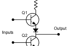
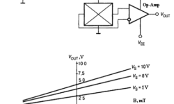
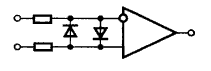
Hall sensors are common sensors of many measuring devices, including linear or angular motion, magnetic field, current, etc. The main convenience of hall sensors is that they don’t have to be mechanically connected to objects. They are also simple, cheap, which makes them attractive in the automotive, manufacturing, and aviation industries. Many manufacturers produce hall sensors: Honeywell, Melexis, Allegro Microsystems, Micronas Intermetall, Siemens, Analog Devices, etc. A typical circuit for connecting Hall sensors One of the simplest is linear Hall sensors that are used for measuring magnetic field strength. Integral hall sensors include a sensor signal amplifier, also temperature compensation, and supply stabilization circuits. Sensor output signal voltage and polarity depend on magnetic field strength and direction. If there is no magnetic field near the sensor, then output is equal to zero. To achieve this differential amplifier has to be used, characteristics will be corrected to be output voltage zero when there is no magnetic field. Other groups of hall sensors have comparator built-in. This allows having digital level signals on output. There can be two types of such hall devices: switches and triggers.

Continue reading

Protection circuits for operational amplifiers

In the specifications of operational amplifiers, there are maximum limits of allowed voltages on pins. Maximum currents are limited as well. So voltage and current they both limit allowed dissipated power Pmax=Umax*Imax. In well-designed circuits, Op Amps should have protection circuits from various overloads like a short circuit, high common phase voltage level in differential inputs, electrostatic charges, etc. Earlier operational amplifiers didn’t have built-in protection circuits, while modern ones have. Today popular operational amplifiers have internal protection circuits built-in, and this makes designers’ life much easier. But protection elements lowers some operational amplifiers like operation speed, dynamic range, and output signal swing level. Because of this, some operational amplifiers may not have internal protection circuits. In this case, you have to take care of it.

Continue reading