Signal sampling mechanism

Sampling is a process when a series of discrete samples represent the continuous-time signal. At the same time, the reconstruction is the reverse process when these samples recreating adequate continuous-time signals. Bellow, the overall process is illustrated. Sampling is a process when the continuous-time signal is recorded every T seconds by multiplying by an impulse train.

Continue reading

From analog to digital signal filtering

A signal filter is an electrical equipment that attenuates the unwanted signal characteristic wave. Filters can be analog or digital. An analog filter processes analog signals. They are mainly arranged with capacitors and resistors. Digital signal filters process digital signals which are quantized. Digital filters are arranged with solid-state components to process the signals. L’s start from analog filters. An Analog filter is a circuit that filters unwanted frequencies. Filtering is done by choosing the circuit transfer function. Simplest analog low pass filter: The current in RC circuit can be calculated as follows:

Continue reading

Frequency response of discrete system

In the previous post, we discussed the impulse response. Impulse response h(n) is a digital system response in the time domain. But there is another characterization of the discrete system – frequency response H(ejω). Frequency response can be calculated form impulse response by formula: This means frequency response is the systems transfer coefficient to every frequency value. Frequency response is a complex function. So this can be evaluated as:

Continue reading

Digital system equation

Back to the DSP thread. Let’s talk about the digital system equation. Every digital system can be described using this equation. The output of the digital filter generally consists of previous inputs and previous outputs. y(n-k) is considered as previous outputs; x(n-p) – previous inputs; ak and b­p – coefficients; This equation is convenient to define the discrete systems and extract various characteristics. Number N defines a discrete filter tap (Tap – A FIR “tap” is simply a coefficient/delay pair). Lets say we have digital filter made of one tap. y(n)=a·y(n-1)+b·x(n) First we calculate filter response function – h(n): Response function is calculated from system reaction to discrete impulse ´(n). So assume that x(n)= ´(n) and y(n)=h(n). Initial conditions: y(-1)=h(-1)=0. Then: h(n)=0 when n<0; h(0)=a·h(-1)+b·´(n)=b; h(1)=a·h(0)+b·´(1)=ab; ……. h(n)= ban where n>0 Lets say we have a=0.7; b=1; Then we get discrete system characteristics: This equation in example describes IIR (Infinite Impulse Response) discrete systems because there is a feedback element a·y(n-1). There is another type of discrete filter – FIR (Finite Impulse Response) Finite response filter equation is much simpler: As you may notice from the equation – the IIR filter has an infinite number of response impulses while the…

Continue reading

Discrete systems in series and parallel

Discrete systems in series We have two discrete systems, and their impulse responses are h1(n) and h2(n). Then when these discrete systems are connected in series, then overall impulse response: Where: As you noticed there were changing made: This is nothing more than convolution of impulse responses of both discrete systems: Discrete systems in parallel If we have two discrete systems connected in parallel: As we see, there is a simple sum of output queues of each discrete system. So we can assume, that the overall impulse response is the sum of systems connected in parallel:

Continue reading

What is a linear system?

A discrete system is nothing more than an algorithm, where input is transformed into output. The output is transformed by operator L(), which describes the discrete system.Let’s see the few most common operators of discrete systems. Delay This means that output queue is delayed by on sample. Multiplication This operator takes each sample of input queue and multiplies by constant a. Sum operator Takes two or more sample queues and adds them in the output. Assuming we can say, that the system is linear if input sum reaction is equal to sum of inputs reactions: The system has stable parameters if:y(n-k)=L(x(n-k)), this means that output delay should be the same as the input.It is obvious that delay, multiply, and sum operators are linear and have stable parameters. We will need them for further lessons.

Continue reading

Understanding of discrete signals

Discrete signals can be generated by software or obtained from the real-world through ADC. Discrete signals are sampled from analog signals. So you get samples in fixed time intervals. The discrete signal is a sequence of numbers. The element number n of the sequence is marked as x(n). The most common number rows: Unit sample sequence You can describe it in Matlab like

Continue reading

Removing 60Hz from ECG using digital band stop filter

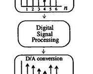
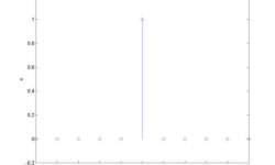
Let’s make a filter, which filters off the 60Hz frequency from the ECG signal. As we know, the American power supply is 60Hz. This is a common noise in biomedical signals while the industrial power supply powers them. This type of noise can be defined easily and can be filtered as parameters of noise are known.Here is one example of how to implement an FIR filter using mathematical tools, like Matlab. This can be done using a microcontroller, like ARM or even AVR, because the frequencies are up to 1 kHz.Initial conditions: f0=60Hz – power supply frequency;fs=500Hz – sampling rate;frequencies who define complex zeros: we get w0=0.754;Positions of complex zeros: Zeros and poles in z plane System Function From it we can calculate filter coefficients: And filter coefficients: b3 = 1; b2 = -2cos(w0); b1 = 1 Also we know that: And here we get filter characteristics: We have a band stop filter at 60Hz, and its jam at 60Hz is -300dB. Bellow is a filter structure: Now using this filter we can filter ECG signal: As you can see, this is a simple FIR filter. In other words, there is nothing more than an average function that doesn’t need…

Continue reading