
In the midst of a global pandemic like covid-19, SARS, or MERS, the most common advice given by health experts is to use handwash or hand sanitizers to clean your hands. Since Covid-19 hit Europe, the increase in sales of hand wash was about 470 percent in March 2020. Hand sanitizer is now a 200-billion-dollar industry, and with the public growing awareness about hygiene to combat viral outbreaks like Covid-19, there is no foreseeable limit to that demand. The origins of hand sanitizer trace back to a 1966 medical facility in Bakersfield, California, when a health care worker combined iso herbal alcohol with a gel to substitute soap and water when it was not readily available.
Electronics has a major application in the area of medical sciences. Every bio-medical device needs electronics help to achieve its purpose, whether a body temperature checking device or a pulse rate/BPM checking device. Medical electronics is one commercial industry segment that necessitates long-term stability as well as dense circuitry. As soon as we think about hand sanitizers, the first thing that come into mind would be how to make it automated using electronics so that no germs can transfer from the hands of one user to other. So, the concept of Automated hand sanitizer came out, and engineers started to work on that and made the devices available at almost every store.
Want to make simple, reliable, and cost-effective automated hand sanitizer at home? This article will help you in that, so let’s start working on automated hand sanitizer. The components that are required for this hand sanitizer are given as
- 5 volts submergible water Pump
- An empty water bottle
- TIP 30/ TIP 32 transistor
- Android cable
- IR obstacle sensor module
- Some wires and water pipe
Sensor PCB Assembly, recommend AiPCBA PCBA manufacturer.
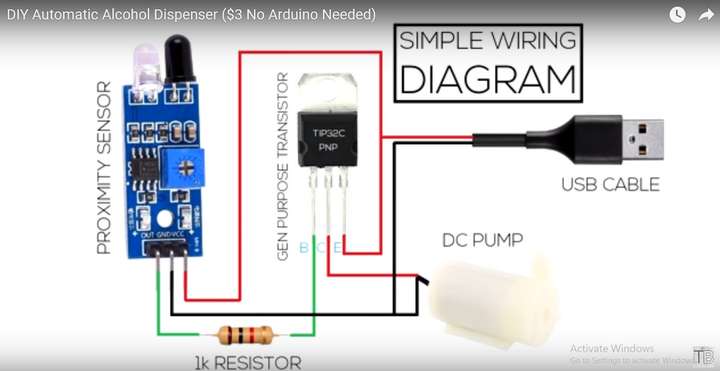
To start assembling, the first thing that we need to do is connect all electronics components. For circuit diagrams or schematics, refer to the image given below.
Try to solder all components according to the schematic diagram. Connect VCC of IR sensor module with the emitter or third pin of Transistor, which further goes to the red wire of android data cable which should be trimmed. Now connect Gnd of IR sensor module with Water pump and then to the black wire of data cable. The output of the IR sensor module is connected with the Base or 1st pin of the Transistor having a resistor in series. Collector or 2nd leg of Transistor is connected with red wire of water pump. Now we are done with the connections. To verify, just plug in the data cable in and 5 volts mobile charger and place hand in front of the IR sensor module, the water pump will turn on. If not, then there is some problem with the connections. Recheck system wiring and confirm according to the schematics provided. After soldering, the system will look like the image shown.
The second step will be to assemble and fix all soldered components in the bottle. First of all, make a hole on the top side of the bottle for water pump wires and water pipe. Now take a small box or container and glue all of the soldered components inbox such that the IR transmitter and receiver led of IR sensor module will be just outside of the box as shown in the image below. As the IR obstacle sensor’s purpose is to detect the hand and then the pump will turn on, some part of the obstacle sensor should be outside of the boxing. Complete Automated hand sanitizer system is shown below in the image.

Now the automated hand sanitizer is ready to work and clean your hands. Here’s a tip, you can use a thick enameled copper wire to hold the water pipe still; this will help you set the water pipe. To understand the working of the system, let’s discuss this system in detail.

TIP32 is a PNP transistor, which will turn on when a LOW signal is provided at its base, and it will turn off when a HIGH signal is provided. We had used a PNP transistor because the IR sensor module output is inverted. IR obstacle sensor will give a HIGH signal in a normal state, and when an obstacle or a hand is detected, it will provide a LOW signal at the output pin. As soon as the PNP transistor detects the LOW signal, it will behave as a switch and let the power pass through it, turning on the water pump. This will let the sanitizer move out through the pipe. Submergible water pump operates from 4 volts to 5.5 volts, so a mobile charger supply is the best choice for the water pump.
Hence one can make this automated touchless hand sanitizer system at home at 5 dollars maximum cost. This will help you and your family to fight through these difficult times of the COVID pandemic.