Microcontroller Brown-out detection
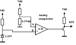
Mostly all microcontrollers have built-in Brown-out Detection (BOD) circuit, which monitors the supply voltage level during operation. BOD circuit is nothing more than the comparator, which compares supply voltage to a fixed trigger level. If the microcontroller doesn’t have an On-Chip Brown-Out detector, then there can be an external circuit used : In the image above, there is a discrete brown-out detector circuit. There are particular IC where additional delay circuitry and hysteresis used to normalize supply voltage may take some time in a real word. Such ICs are cheaper than one built from discrete components.