avrdude-gui another easy way to program AVR microcontrollers
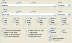
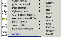
Avrdude-GUI is a simple graphical user interface(GUI) for avrdude, a command-line tool running on several OS to program the Atmel AVR Microcontrollers. AVRDUDE-GUI is included in the WinAVR toolset and can be used separately to program AVR chips avoiding the command line as it has to be done with plain AVRDUDE. This program has no installation or uninstallation routines. It just has to be in the directory where the avrdude is located. It has almost all functions needed to program AVR microcontrollers effectively. A few things that need to be done are reading fuses and working with single fuse bits. Now you have to define whole fuse bytes what is not very convenient.