Reading AVR button status using WinAVR

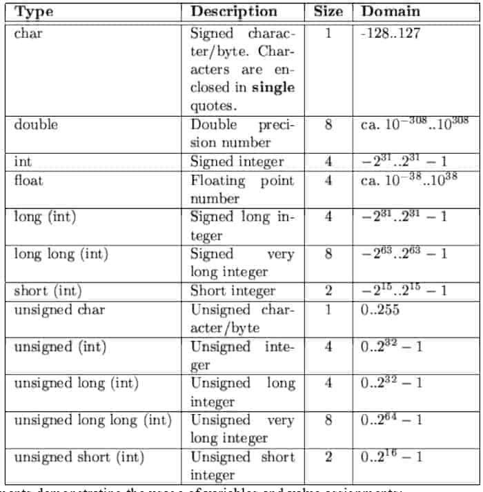
If you want to bring some interactivity to your embedded projects, one option is to add buttons. This allows you to control program flow, set parameters, and much more. Few words about AVR ports. AVR Port pins can be configured as input or output. See table for all general pin configurations: DDRx register is the so-called direction register; PORTx – is port output register; PINx – is pin input register;

Continue reading

Simple routine how to store data in microcontroller flash and read from it using WinAVR

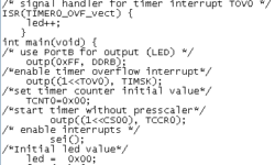
I’ve been asked about how to store data tables in flash memory using the avr-GCC toolset. I decided to post an answer here. Might be someone who find this useful. To demonstrate this I have set up a project using the VMLAB simulator. The files you can download from here: Small project using VMLAB simulator So I created a project in VMLAB. It will help if you read my previous article ho to do this: Using VMLAB as a virtual oscilloscope In project window I have connected 8 LED’s to port D by typing this: D1 VDD PD0 D2 VDD PD1 D3 VDD PD2 D4 VDD PD3 D5 VDD PD4 D6 VDD PD5 D7 VDD PD6 D8 VDD PD7 Then I wrote a simple C program: In program you see, that data can be stored in flash memory using data describing sentence: To make PROGMEM macro work you have to include library pgmspace.h. Bellow you see result of simulation in VMLAB environment:

Continue reading

Internal microcontroller ADC

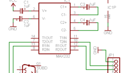
Many microcontrollers contain internal on-chip ADC. Typical devices would be Atmel Atmega series microcontrollers like Atmega8 and further. Internal ADC is a successive way to integrate the analog world into your embedded systems using only one microcontroller die. Many applications don’t require high speed or high accuracy ADC conversions; thus, on-chip ADC is the best choice. Let’s look at Atmega8. It contains a 10-bit approximation ADC with an analog input multiplexer of 8-single-ended input voltage (refers to 0V) channels.

Continue reading

How to measure wind direction

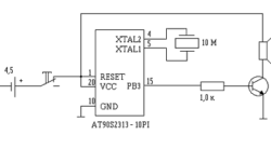
I found this wind direction measurement circuit simple and interesting. If you are doing some home automation project, this might be another sensor included in your project. For Wind direction measurement, you will need a circle from some material (you might even use a CD.) Then stick an arrow on top. One end of the arrow should have a fin. Another end of the arrow should have a piece of magnet. Then put eight magnetic sensors around the circle in the magnet’s way. See drawing:

Continue reading

Creating custom LCD characters using WinAVR

Standard LCD modules come with built-in Character MAP stored in LCD ROM memory. There are plenty of characters for your needs, but you may still need some special ones like backslashes or some symbols in different languages. This LCD has a reserved RAM area for storing eight 5×7 dot matrix character patterns. In the table above, this area is in the first column with addresses starting from 0 to 7 (from 0b00000000 to 0b00000111). This means that you can define any characters in these 8 fields as you like and use them by calling them by addresses from 0 to 7.

Continue reading

Always read newest datasheets

Reading of datasheets is or should be an important part of designing electronic devices. Reading datasheets is necessary for writing device requirements, planning budget, and selecting suitable components. Datasheets of each component may be found in manufacturers website. Once you’ve selected a suitable component, be sure that you read the datasheet and understand everything in it. Otherwise, you may miss some critical parts that could ruin all your plans. It is better to find errors before you start designing than after. Another important issue is that always check for newest datasheets and errata – datasheet bug lists. It is not good practice to use your old datasheets from your hard drive archive or other places. These datasheets may contain bugs. Just download the newest microcontroller or other semiconductor datasheet and compare to yours downloaded let’s say a year ago. Errata’s and datasheet changes are usually listed at the end of the datasheet. You may look at this and find out what would you miss with old datasheets. The electric characteristics maybe are the same, but there may be configuration bugs or even discovered bugs in hardware and proposed workarounds to avoid them. So be critical and don’t rely blindly on…

Continue reading

How to read electronic circuits

In electronic circuit drawings, there are two types of objects: component symbols and nets. Nets represent wires connecting the components – which represent physical devices. In the example below, we see component type MAX3232. U2 is a reference label of a component. Electronic component usually has pins. Pins always have their numbers starting from 1. Pins also have their names. They are usually written inside component blocks like C1+. For this particular component, we used the U2 label. U (or IC) label applies to all semiconductors. But you know that resistors usually are labeled as R1, R3. Capacitors C1, C2, Diodes – D1, D2, Transistors Q1, Q2, Crystals – X1, X2, X3, Jumpers J1, J2, J3, Inductors L1, L2.

Continue reading

Generic PCB design guidelines

How repeatedly make good PCB? Many hobbyists face this issue every time they are prototyping their ideas. Designing the PCB layout (it doesn’t matter it is a through-hole or surface mount) may be a tricky task, especially when dealing with dimensions like 0.2mm tracks or 0.5mm surface-mount pitches. A laser printer, plotting, or other similar transfer technologies can’t deal with such dimensions. After I have tried the photographic method of PCB artwork transfer, I don’t even want to touch the Iron and laser printer. Using photosensitive laminate and single transparent media, I can repeatedly make any number of PCBs. The benefits of using photographic methods are as follows:

Continue reading

Design and Implementation of DTMF Detector

Telephone units are ubiquitous. They can be found in almost every house. In some houses with many rooms, a line is paralleled so that anybody can receive and make calls from different rooms. Their presence could be used for other purposes instead of making call per se. This module’s application can be found in the smart home automatic system incorporating a telephone unit as an input module. Using a telephone unit, somebody can control a remote system, as far as the telephone line can reach. To do so, such an interface between the telephone line and the control system is needed. DTMF Detector 2.0 is designed for this purpose. Description DTMF Detector 2.0 is a microcontroller system extension module that detects TMF tones and then decodes the tones into coded binary digits. Using DTMF Decoder, the 2.0 design engineer could interface the analog signal of the telephone line with the microcontroller system’s digital logic in a straight-ahead manner. Module Specifications The module specifications are as follows: 1. Input: DTMF tones from telephone line (analog signal) 2. Output: Decoded binary digits which correspond with DTMF tones. Block Diagram Figure 1 shows the block diagram of DTMF Detector 2.0. The module consists…

Continue reading

7-Segments-Board for Embedded Systems

Design and Implementation of 7-Segments-Board 1.0 – An Extension Module for Embedded System Prototype Introduction When developing embedded systems, it would be helpful if we could have a module for monitoring purposes. For instance, let say that your system has to process data streams. In the testing and verification step, we need to compare each input and output bytes to verify that your system is doing right. Having a monitor module is surely a great help for engineers. Some development board has monitor module integrated, such as Altera UP1X FPGA Development Board. Inspired by its usage and benefit of such a monitor, 7-Segments-Board 1.0 is designed as an extension module for embedded system prototypes. Description 7-Segments-Board 1.0 is a low-cost, low-power MCU extension module for monitoring purposes. It aims to help engineers doing the firmware testing and debugging on hardware prototypes. For those who build microcontroller prototype devices from scratch and do not have access to sophisticated debugging instruments, using this module would make the testing and verification process less painful. 7-Segments-Board 1.0 is designed for an 8-bit microcontroller system. Module Specifications The module specifications are as follows: Input: General purpose push-button (PB) switches (dry contact). Output: Seven-segments LED to…

Continue reading