Ultrasound transducers for measuring distance

Ultrasounds transducers for measuring distances are commonly used in robotics, automotive parking sonars. Ultrasound distance measuring is non -contact measuring method – radiation and reception of ultrasound waves. Ultrasound waves are mechanical acoustic waves with frequencies more than 20kHz. Normally humans cannot hear frequencies above 20kHz, while some animals can. For instance, bats use ultrasound location of objects. Dolphins communicate with each other using ultrasound signals. Ultrasound interacts with a hard body, and part of incoming wave energy is reflected; in other words – it is backscattered. So direct wave towards an object is backscattered widely – up to 180°. If the object is moving – the received frequency differs because of the Doppler effect. Let’s say simple example – parking sonar. Distance to object can be calculated very simply by the formula:

Continue reading

Avoid noises in mixed signal design

Today most of all embedded systems consist of two-part circuitry – digital and analog. The Digital part is usually the controller, its timing circuit, and other input-output devices. Frequently there is an analog part on the same board like ADC, OP amplifiers, sensors, and other analog circuitry. Such designs are called mixed-signal designs. Where digital and analog parts meet – the grounding problems start. The fact is that each conductor has its own impedance, so any current flowing results in voltage drops. Ground wires and planes aren’t exceptions. Digital and analog grounds can generate significant electromagnetic radiation that adds noises to signals we need. So the overall system quality drops because o poor design. In a good design, the analog ground plane and the digital ground plane should be separated. With multilayer PCB, this can be done very easily. Another issue is that digital signal traces shouldn’t cross analog ground, and analog signal wires shouldn’t cross the digital ground plane area. Of course, try to avoid aligning digital and analog wires as they can catch each other radiated noise.

Continue reading

Eagle CAD PCB footprints for audio processors TDA7313 and TDA7315

TDA7313 and TDA7315 are digital controlled audio processors used in applications where digital control of audio is needed. TDA7313 and TDA7315 are pretty the same just TDA7313 is more complex by having 3 stereo input channels and two outputs (front and rare). Both chips have volume control (step=1.25dB), tone (bass and treble) balance, independent faders for each output processor. Also, there is loudness functionality. TDA7313 and TDA7315 have low distortion and low noise, making them ideal for quality audio applications for car audio and Hi-FI systems. MCU can control both chips via the I2C(TWI) protocol. This makes it easy to interface microcontrollers with additional features like LCD, buttons. Or control directly from PC using RS232 or another interface. Both chips can be found in DIP or SO packages. Here are Eagle libraries of both digital audio processors that I have made. tda7315.zip(2kB) tda7313.zip(2kB) I have intent to make a control board with TDA7315 with LCD and button control using an Atmega8 microcontroller.

Continue reading

Calculating of electrical heating elements

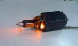
Electrical heating elements are often used for teapots, irons, electric ovens, soldering irons, etc. When projecting designs with electric heating elements, you need to do some calculations that may seem difficult at first glance. But when looking more deeply, this becomes a simple task. We know that electric heating is a result of the current flow in wire with some resistance. The resulting heat is work done by electric current. Work A(J) can be calculated by the formula:

Continue reading

Calculating wire diameter for maximum current

When selecting wire diameter, we usually look for cross-reference tables to find the recommended wire diameter for the maximum current drive. But sometimes maybe more useful to calculate by formula than look into the tables. This way, you can have more accurate results. There is nothing new, just simple physics. Wire resistance (Ω)is calculated as follows:

Continue reading

Electric circuits analogy to water pipes

Sometimes calculating some objects’ parameters and behavior may be much easier when using analogy to objects with well-developed theory and calculation methodology. In an earlier article, we analyzed power dissipation of electronic devices using Ohms law where Voltage=temperature, Current=Dissipation, and Resistance=Thermal resistance. This time let’s look at how electronic devices can be transformed into water pipes and vice versa. Let’s take the Voltage source. A simple battery is like a water pump which provides Pressure (a voltage analogy): The second electronic element is a resistor. Resistors can be imagined as water pipes with a smaller aperture. The higher resistance is – the smaller aperture of the pipe:

Continue reading

Thermal analysis of semiconductor devices-when do you need heat-sinks

Every electronics constructor and engineer knows that electronic devices like IC’s voltage regulators and CPU heat up. Temperature is a critical parameter for reliable system operation. System reliability is very closely related to devise temperature high or low. While temperature increases, the reliability drops exponentially. If you look in device datasheets, you will find a recommended Operating temperature range. For instance, the Voltage regulator 7805 can normally operate at 0 – 70°C temperature range when maximum Junction Temperature can reach 150°C. So how is the operating temperature range calculated? It is not as difficult as it may look like. We know that temperature is analogous to voltage, thermal resistance changed to electric resistance, power dissipation is as current, then:

Continue reading

PCB construction methods for embedded controllers

The most common method is of constructing embedded controller systems is a Printed Circuit Board (PCB). All electronics know that simple PCB is constructed of insulating material like epoxy impregnated glass cloth with a thin copper sheet(s) on one or both sides. There are many conflicts about requirements on how to design interconnection patterns of PCB. But the main purpose for all is to make PCB reliable, effective and producible. If the circuit operates at a low speed, requirements are not as strict as for high-frequency devices where the parasitic effect cannot be ignored. Each PCB stray has its own resistance, capacitance, and inductance. These are the main effect that distorts the signals.

Continue reading

Schmitt trigger VS simple inverter

Schmitt trigger is a special logical element adjusted to work with analog input signals. The primary purpose of Schmitt triggers was to restore the shape of digital signals. Because of the transmission line effect, digital shape transforms from square to trapezoid or triangle or more complex signal. Of course, during transmission, signals become noisy and distorted. Schmitt trigger is a comparator circuit, but positive feedback results in hysteresis and memory effect. Comparing to simple logical elements, Schmitt triggers have two threshold levels. Between these threshold values U1 and U2, the state of output doesn’t change the so-called hysteresis. Such an effect stabilizes output against rapid triggering by noise. Bellow is two characteristics compared of simple logical inverter and Schmitt trigger inverter:

Continue reading

Marking of Digital IC chips

There are currently huge amounts of different digital IC chips available in the market, starting from the simplest logical elements and ending with processors and gate arrays (FPGA). Of course, there also are lots of IC manufacturers offering IC’s. Many of them are specialized and won’t be reviewed here. Let’s limit ourselves to smaller, more general digital chips, basically TTL 74series. This series is produced by many manufacturers like Texas Instruments (TI).Common marking: Manufacturer identifier indicates the manufacturer name;

Continue reading