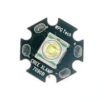
Usually, when we need to drive low power LEDs, we don’t care much about power losses. What we do we add a current limiting resistor, and that’s enough. For instance, for 20mA LED, we choose between 300Ω-1kΩ resistor when powering from 5V. But a different situation is with power LEDs. The currents are much more prominent here, like 1A and more. Adding a resistor to limit the current isn’t an option because power losses become significant. Here you need a constant current driver to drive it safely without wasting energy. It happens that I have Cree XR-E Q5 XLAPM-7090 LED lying around. It requires a 3.7V driving voltage and can take up to 1A current.
There are several light intensities given at specific currents:
- 350mA: 107~114lm
- 700mA: 171.2~182.4lm
- 1000mA: 214 ~ 228lm
LED is placed on PCB with a metallic bottom for heat dissipation. These things get hot and maybe damaged without heatsinking. There are lots of specialized LED driver IC’s you can get. They all compete with price and efficiency. The main aim of all Led drivers is to ensure a stable current source. It has to be temperature independent so it would stay the same in different conditions. It is better to rely on special chips, especially if your designed product must be reliable. But what if you want only to drive power LED without spending a dime on parts.
Building a LED driver circuit
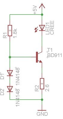
In my situation, I want to drive LED at 0.3A to get decent light and still avoid using a heatsink. So I need to build a current source capable of providing 0.3A. In my drawer, I found a BD911 power NPN transistor, which I’m going to use. You don’t need that much as this transistor can handle up to 15A of current. Probably simplest constant current circuit is based on NPN transistor, and couple diodes are as follows:
In this circuit, two diodes at the transistor base provide a constant 1.4V (2×0.7V) voltage drop. Base-Emitter voltage drop is approximately Vbe=0.7V, and the rest 0.7V goes to R2 resistor. This becomes convenient because we can calculate its value using a simple formula:
If we want to drive LED with 0.3A, then we need R=2.3Ω. This is a current limiting resistor for the LED. It is going to dissipate 0.7W of power. To be sure I choose at least twice as much power resistor. Now how about R1? From the datasheet, we can find that the current gain is about 250. So to get 0.3A collector current, we need to supply base with 0.3A/250= 1.2mA. Having a base current, we can calculate R1. Don’t forget that diodes also require some current to operate properly. 1mA should be enough to provide a forward voltage drop. Then R1 can be calculated as follows:
I could only find 2.6Ω current limiting resistor. So with it I can drive LED with 260mA current.
Testing LED driver
Lets build a circuit and see if it works. Assembled and powered with 5V supply.
The measured Led current is 240mA. The measured current is a bit smaller because the voltage drop on diodes were less than 1.4V and thus less voltage left for the emitter. Such current is sufficient to drive Led without a heatsink. If more current is provided it gets boiling.
Also, I measured the current draw from the power supply which is around 245mA. Let us see how efficient circuit is. LED voltage drop is 3.7V so power usage:
Supply power:
So we lose:
Or we can say that the circuit is 72% efficient:
Takeaway
For higher efficiency, it would be better to use MOSFET with low Rds resistance. Practically this circuit works stably in a reasonable power voltage range. Powering from 5 to 15V shouldn’t be a problem. But with more supply voltage, you dissipate more power with the transistor, so you get less efficiency.


Your circuit is actually less efficient than just using a big power resistor. The power that would usually be consumed by the resistor is just shifted to the transistor and the extra circuitry takes some power too.
If you want 240mA, you need (5-3.7)/0.24 = 5.4 ohm
Using 5.6 ohm:
I = (5-3.7)/5.6 = 232mA
Pled = 0.232*3.7 = 859mA
Eff = 0.859 / (5*0.232) = 74%
Using 5.1 ohm:
I = (5-3.7)/5.1 = 254mA
Pled = 0.254*3.7 = 943mA
Eff = 0.943 / (5*0.254) = 74.3%
Your circuit is still useful because when you start getting up to serious currents it’s often easier to heatsink a power transistor than it is to buy a multi-watt rated resistor. If you want to improve your efficiency then you need to string LEDs in series (minimise the voltage drop on the resistor) or use a dedicated switching LED driver.
Correction, those powers should be in mW 🙂
You have a point James. It’s less efficient, I see only one benefit with such circuit, that it retains same current on supply voltage change and also on temperature change. With simple resistor only if you double the power supply voltage you get double the current flowing through the led. I’d say constant current driver you are save that way.
For efficiency without argue it is better to use dedicated LED driver.
I was wondering if this circuit (or a variation thereof) could be used to drive a diode laser ?
I have removed a small diode laser from a dvd player and I wish to drive it without breaking it.
Isaac Lehane
Hi, I am building a battery powered LED torch with 4X1.2V 1200mA batteries, and 3X3W LEDs I am trying hard to find a driver which could do the job of connecting them together
the LEDs I have are,
LED, HIGH POWER, 5000K, 70CRI, 275LM
Series: LUXEON TX
LED Colour: White
Luminous Flux @ Test: 369lm
Forward Current @ Test: 1A
Forward Current If Max: 1.2A
Forward Voltage @ Test: 2.86V.
could you please help me what should be the specifications of the driver??
Such circuit will work for laser diode, but you should adjust it for 1A current. You need to replace R2 with 0.7Ω resistor. Resistor will dissipate 0.7 W, so you need to use at least 2W resistor. As we discussed, this is not efficient driver especially if you use battery to power it.
Hi what would you do if you wanted 4V and 14A from the driver. Is it possible?
sorry forgot to subscribe.
Hi, i wanted to know if there are other npn transistor that can be used if i can a BD911?
*cannot find
An ancient varietie of this circuit is to replace the 2 diode’s with another NPN.
Connect the base to the Emitter of the other transistor.
But nowaday’s:
Use some SMPS circuit from ali. Such as LM2676 based “battery chargers”.
The 3 pot versions have current limiting build in.
There are also a gazillion IC’s designed specifically for led lightning.