X-10 interface for home automation projects

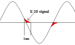
Simply speaking X10 protocol allows transmitting data over power lines. X10 uses a PLC(Power Line Carrier) technology. How does this work? The specification says that each time a 60Hz AC signal crosses the zero line,, a 120kHz burst is is transmitted with a duration of 1ms. One crossing burst forms one information bit. Simply speaking if we needs to form “1” you need to burst at the first crossing but not at second and for “0” is reversed pattern – you need to burst at the second cross but none on first.

Continue reading

DIY 4x22W car audio amplifier based on TDA7384

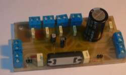
I decided to make a pretty simple but powerful enough audio amplifier. For this, I’ve chosen quad-bridge car audio amplifier IC – TDA7384, which has four input and four output channels with a power capability of 4x35W. If connected to a car battery where the operating voltage is about 13.2V, then each channel can give 22W what is more than enough for me. This amplifier I probably will use to test audio processor TDA7313, which is still in the development phase. I didn’t find much information about this chip on the internet, so I decided to build it and try it independently.

Continue reading

Programming microcontrollers AduC70xx using boot-loader and ARMWSD utility

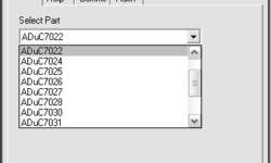
Firmware for AduC70xx ARM microcontrollers can be uploaded using a built-in boot-loader. To work with boot-loader, Analog Devices offer a small free program, ARMWSD working under the windows system. The program doesn’t require installation. ARMED communicates with AduC70xx via COM-port. Simple programming steps looks like this: Connect target board to PC COM port; Go to Configure->Parts and select AduC part: Then go to Configure->Comms and select serial port and baud rate:

Continue reading

Integral Hall sensors

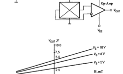
Hall sensors are common sensors of many measuring devices, including linear or angular motion, magnetic field, current, etc. The main convenience of hall sensors is that they don’t have to be mechanically connected to objects. They are also simple, cheap, which makes them attractive in the automotive, manufacturing, and aviation industries. Many manufacturers produce hall sensors: Honeywell, Melexis, Allegro Microsystems, Micronas Intermetall, Siemens, Analog Devices, etc. A typical circuit for connecting Hall sensors One of the simplest is linear Hall sensors that are used for measuring magnetic field strength. Integral hall sensors include a sensor signal amplifier, also temperature compensation, and supply stabilization circuits. Sensor output signal voltage and polarity depend on magnetic field strength and direction. If there is no magnetic field near the sensor, then output is equal to zero. To achieve this differential amplifier has to be used, characteristics will be corrected to be output voltage zero when there is no magnetic field. Other groups of hall sensors have comparator built-in. This allows having digital level signals on output. There can be two types of such hall devices: switches and triggers.

Continue reading
Protection circuits for operational amplifiers

In the specifications of operational amplifiers, there are maximum limits of allowed voltages on pins. Maximum currents are limited as well. So voltage and current they both limit allowed dissipated power Pmax=Umax*Imax. In well-designed circuits, Op Amps should have protection circuits from various overloads like a short circuit, high common phase voltage level in differential inputs, electrostatic charges, etc. Earlier operational amplifiers didn’t have built-in protection circuits, while modern ones have. Today popular operational amplifiers have internal protection circuits built-in, and this makes designers’ life much easier. But protection elements lowers some operational amplifiers like operation speed, dynamic range, and output signal swing level. Because of this, some operational amplifiers may not have internal protection circuits. In this case, you have to take care of it.

Continue reading

Switching step-up and step-down regulators

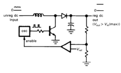
All regular voltage regulators (like 7805) have several disadvantages like output voltage is always lower than input, and some power is dissipated in the control element. Dissipated power is approximately equal to I(Vin-Vout). There is another way to generate a regulated voltage. The method is different from the previous one. A transistor operates as a saturated switch in a switching regulator, which periodically applies the full unregulated voltage across an inductor in short intervals. During each pulse, inductor current builds up, storing energy on its magnetic field: Inductor also smooths the output voltage. Feedback circuit with comparator compares the output voltage with reference and this way changes oscillators pulse width or frequency.

Continue reading

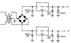
Dual polarity power supply source

Most op-amp circuits run from the symmetrical bipolar supply source, let’s say ±15V. The simplest way to generate symmetrical split supplies is to use a pair of 3 terminal voltage regulators. For instance, let’s take two voltage regulators: 7815 and 7915. If you need an adjustable variant of dual polarity regulated voltage source, you can use 317 and 337 adjustable regulators, where you can trim voltage with a voltage divider, which consists of two higher accuracy resistors:

Continue reading

Interrupt system of ARM LPC2000 microcontrollers

Microcontrollers aren’t imaginable without interrupts. The arm isn’t an exception. There were SWI exceptions mentioned in earlier articles, but there are two more sources of exceptions: IRQ(General Purpose Interrupt) and FIQ(Fast Interrupt). ARM Pin Connect Block All I/O pins of LPC2000 ARM can be multiplexed to several functions via pin select block. Pin selection bloc allows selections up to three more other functions except for GPIO. Pin Connect block gives flexibility to ARM MCU because each PIN can have different functionality. After reset, all pins are configured as GPIO. As the example above, you can see that the P.1 pin function can be assigned by PINSEL0 register 3 and 2-bit configurations. So if you write PINSEL0|=(1<<3)|(1<<2), then the pin will be assigned to the EINT0 function. Pretty simple. So before using External interrupt EINT0, first, you have to select the pin function for the P0.1 pin.

Continue reading

Power modes of LPC2000 ARM MCU

Power modes especially become more important where power saving is needed. All common microcontrollers have several power control modes.LPC21xx series microcontrollers have to reduced power modes: idle and power-down mode. Idle mode Execution of instructions is suspended until reset or another interrupt signal occurs. In idle mode, peripheral devices (for instance, timer) are running and may generate interrupts that cause the processor to resume execution. So idle mode eliminates power used by the processor itself, memory system, and internal buses.

Continue reading

Clocking ARM with Crystal oscillator and PLL

ARM microcontrollers can be clocked in several different ways. One way is to use an external clock with a duty cycle of 50-50 and a frequency range from 1MHz to 50MHz (LPC21xx series) connected to the XTAL1 pin. Another way is to connect the External crystal oscillator, but its range is lower (1MHz to 30MHz for the LPC21xx series). And last but not least is the on-chip PLL oscillator, then external clock source frequency should not exceed range from 10MHz to 25MHz. Let’s analyze more deeply each clocking mechanism. In the picture above there is fosc selection diagram shown.

Continue reading