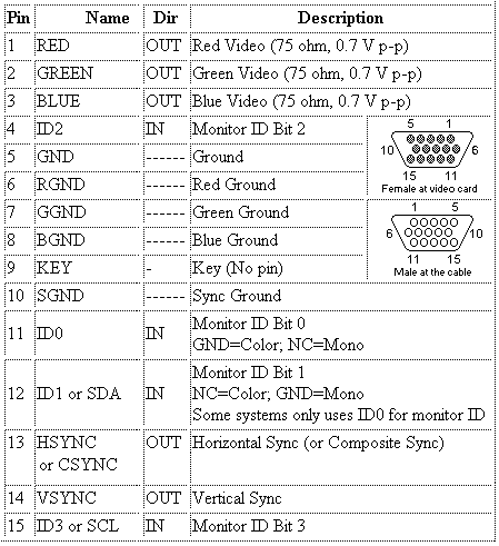
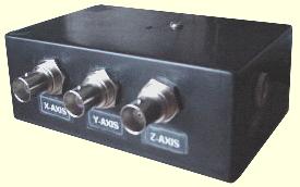
This is a fun project I found on Jon’s antique radios web-page. He has managed to convert the VGA output signal from PC to X Y X oscilloscope signal. Converting the VGA RGB signal to a synchronized oscilloscope input signal is pretty easy because VGA has two sync signals separate from RGB signals. Look at pin-out of VGA cable:

Sync signals make things much easier as there is no need for additional sync signal generators – thus circuit becomes pretty simple without any programmable components:

The sync signals are taken from the VGA cable trigger sweep tooth signal (555 timers) generators. These generators generate ram signals for oscilloscope, which enable the creation of a raster pattern. The vertical generator frequency is around 75Hz, and horizontal about 35kHz is used as horizontal sync pulses. Output sync (75Hz) is fed to oscilloscope Y-axis, and 35kHz sync signal is fed to the X-axis of the oscilloscope. The circuit is ready for 800 x 600 at a 75Hz refresh rate. For different configurations, you might need to adjust horizontal and vertical sync 555timers RC circuits.
The RGB signal is converted to a monochrome signal and fed to the Z-axis of the oscilloscope as intensity.

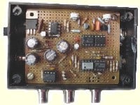
Inside the box:

Be sure that you turn the PC before switching the oscilloscope ON; otherwise, without a PC sync signal, you will get a bright dot on the Oscilloscope screen that can burn the phosphor. When turning off – turn the oscilloscope first before turning off the PC.
Circuit is sensitive to voltage swings. Be sure that you have stabile +5V.
PC desktop image:

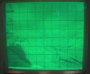
The image on oscilloscope:

References: Jon’s antique radios.


This is great project :-). I wouldn’t believe ordinary oscilloscope is capable of displaying fast VGA signal in XY mode.
btw, you might be interested in some VGA Microcontroller projects at http://www.tinyvga.com …
smirdiigs tev tas suuds sanaacis, es no govs suudiem labaaku vareetu uztaisiit