Building AVR Jtag clone
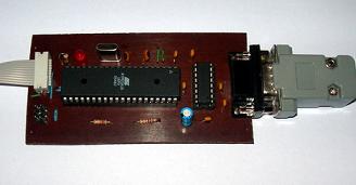
Finally, I found some time to finish the AVRJTAG clone. It was hanging for a while on a breadboard with a bunch of wires. I have made an Eagle CAD project with a PCB layout you will find at the article’s bottom.

I didn’t change the circuit very much from the previous, just added ISP header(but didn’t have a chance to test it) and transferred to Eagle project as I didn’t find one ready to build:

The description on how to update firmware is in the previous article <Build your own AVR JTAG ICE clone>.
Testing AVR Jtag in action
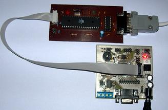
Let’s give a test run. Using Jtag is as easy as using the AVR Studio simulator. The difference is that you have to connect the JTAG adapter to the target board. In my case, I am using the Atmega128L Piconomic board.

On the board, there is a connector for the Jtag adapter/debugger. The second option is to set the JTAGEN fuse for the target MCU.

Otherwise, AVR Studio will throw an error:

After the hardware is ready, let us try with the sample project. For this, create the AVR-GCC project in the AVRStudio environment. Then select debugger platform (JTAG ICE) and AVR MCU(in my case Atmega128):

Write a simple program which controls a button and LED: button_led.c
Compile the program and start the debugger with the run command. You can work with JTAG debugger as with simulator – stepping, auto-stepping, break-points, memory views, changing register and memory values, and so on.

One difference that the program is running in the real world. So it is easy to debug the platform with additional peripherals connected to MCU. And, of course, real-time execution.
Project files for Eagle CAD and boot-loader are here: avr_jtag_clone.zip


And how does it work with VCC connected to reset?
The ATmega16 Vcc,AVCC must be connected to the +5V net.
The AVRISP connector 5 pin(reset), should be connected to the JTAG connector 6pin (nSRST), not to the ATmega16 RST net.
AVR ISP connector 5 pin is OK I think as ISP head is only used to upload bootloader to adapter itself via ISP interface. It has nothing to do with JTAG. But VCC and AVCC circuit in picture is connected improperly. I will look at my original circuit if there is same problem, because my adapter works OK. Thanks Laszlo for notice.
Yep same error in my board. Can anyone tell my why it works for me with VCC connected to Reset pin? I have fixed circuit and pcb files. Thank you for your notice.
probably ot works because the output pins have some diodes for protection, and draws the power from your target board.
I have a AVRJTAGICE mkII and that has this feature, you just connect a small adapter to the JTAG connector,and select ISP mode.
I tought that the JTAGICE has this feature to.
Hy,
I’ve build this JTAG loaded the bootloader, when I try to upgrade the ATmega163 is selected, and I get a verification error to, and offcourse I can’t connect to the JTAG adapter trough AVRStudio.
Please explain this errors, and give some answer.
Regards, Laszlo
I build the PCB and load the bootloader and the upgrade files into mega16 by following your instructions. Fuse was programed the same as you describled.
but when I try to connect it to another Mega16(jtag enabled) to test. it comes with a error message:”cannot connect JTAG ICE from port x” (all available ports were tested)
The wire connection is good, and the target mega16 jtag connection is good, I dont understand why it didn’t work.
please help me!!!!
Hi,
I made this JTAG ICE and everything seem to be fine, but when I build mentioned “button_led.c” and start debugging, program pointer appears out of program range (see screenshots http://www.imagecross.com/myspace-image-hosting-viewer-d.php?id=3145Screenshot-0.gif , http://www.imagecross.com/myspace-image-hosting-viewer-d.php?id=5241Screenshot-1.gif and http://www.imagecross.com/myspace-image-hosting-viewer-d.php?id=8699Screenshot-2.gif ).
Any idea what is wrong? After two days of testing I had no solution. Realy appreciate any hint. Thanks.
Problem found! 🙂 I made mistake with connecting external crystal and setting FUSE to external CLOCK. After changing FUSEs all working great. Sorry 🙂
Nice to hear that. Good luck.
Hi :), juz wondering whether this AVRJTAG works with ATMega1280/1281/2560/2561? Has anyone try to use this JTAG for these chips?
I’ve build this JTAG loaded the bootloader, when I try to upgrade the ATmega163 is selected, and I get a verification error to, and offcourse I can’t connect to the JTAG adapter trough AVRStudio.
Please explain this errors, and give some answer.
please tell me could I use Max232 intant of Max3232,because I havn’t found it .
Yes it has to be MAX232.
Double check the fuses – it should work.
I built the JTAG, downloaded the bootice16_rom into the mega16, set the fuses as described in the page, but when i try to upgrade the soft i get that the device is an mega163 and an error about no able to erase the device at the end of the progress bar. I am using an mega16 but the 8 mhz maxium version. I sounds like the same described in a previous post.
Upgrade error:
The complete text of the error is: Adress: 0x0000, expected 0x940c, Received: 0xffff
Another diagnosis, it is so strange because i can read flash and eeprom using de avrprog of the avrstudio via the serial port. In the other hand, i downloaded the bootloader containded into avr_jtag_clone.zip. So besides the error of the incorrect micro version, could be that there is a problem with the programming voltages. The Pcb is the attached in the quoted file. I will keep trying another possibilites.
Maybe you used a bootloader for mega16 instead of mega163? Hard to say right now where is a problem.
I get the “No supported board found, AVR Prog version 1.40″ message†when selecting AVRProg.
i havent got any pony prog hw, but then a jtagice mkII.
i have to make a cheap programmer for atmega128L.
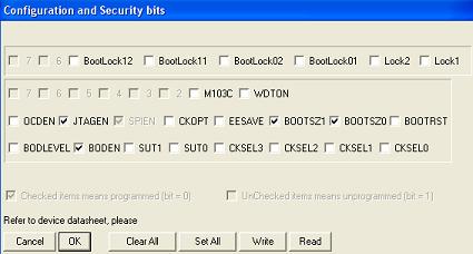
could anyone show some picture about conf. and sec. bits window as the avr studio shows it?
Hi. I’ve made this JTAGice but I get “Not supported board found. AVRprog version 1.40”. I get this massage even when no board is connected to my PC. I’ve made my own target board with a new Atmega16. I’ve programmed the bootloader to another Atmega16, which I placed in the Jtag board. I’ve got power supply wherever I need one. Still no result from my attempts. Can you give me some directions. Thanks.
I tried this JTAG, it’s create. And I also edited this JTAG into the USB version because my laptop do not has the COM port.
It really useful to remove bugs in your source code.
But the among of support chip is small, only 8 chips in AVR 4.07 and 9 chips in AVR 4.14.
Anyway, thanks for your job scienceprog!
I am starting to build other type od JTAG which can support more AVR chip.
Luong Vu Dang Quang
Hi, is this AVRJTAG works with ATMega48/88/168, has anyone try to use it for these microcontroller?
same error as angle
I’ve build this JTAG loaded the bootloader, when I try to upgrade the ATmega163 is selected, and I get a verification error to, and offcourse I can’t connect to the JTAG adapter trough AVRStudio.
Please explain this errors, and give some answer.
AVR JTAG ICE MKII Clone
No one answer that “Can mega32 be used instead of Mega16”?I also have a lot of meag32 but no mega16.
You can use it,but you have to recompile boot loader for your controller with good frequency.:)
Hi, Can I use this programmer for XMEGA?
2 JTAG CLONE error: Test connection VCC to PA2…
If You have any problems with AVR JtagICE clone, built as above, check on site http://aquaticus.info/jtag (few pages).There is proper fuse setting (not as look on Ponyprog), and hex file with complete program which dont need update (identical with update from last versiom of AVR Studio 4). (Update go well, and verify also) Only difference is that pin 21 is connected over 1k to jumper (normal – bootloader), but if You program BOOTRST fuse to “1” (inactive), works also without jumper.
hi,
I made my jtag ice from this website several years ago.
Now i want to build it again.
In the old version there was a resistor attached to pin 38 of atmega 16. is there any change?
can i use old jtag to burn boot loader in the new one?
Haven’t used this clone for long time. Iguess ti should work same. And yes tou should be able to program new adapter with old one. Anyway you will need another programmer to set fuses on target.