How to describe embedded software design using diagrams and pseudo-code
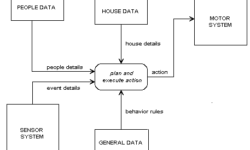
When designing embedded hardware, you probably want to visually express what embedded software will be performing and how different functions depend on each other. How to make software documentation simple, clear, and informative. If you are a developer, you may want to explain your ideas understandably without loads of code text. Depending on what level of information has to be provided, you may choose any of the following. Data Flow Diagram Data flow diagrams are used to see the processes and what data is transferred between different functions. This way, each process or function is expressed as a block (or any other shape), while lines show what information passes between processes. As you can see in the example figure simple data flow diagram is presented. Without program code, it is easy to read how the program operates:

Continue reading

Microwire compared to SPI and I2C

Microwire is a three-wire serial interface used by National Semiconductor in its COPS processor family. The three signals are SI (serial input), SO (serial output), and SK (serial clock). SI and SO are input to and output from the processor, respectively. The processor clocks data to the peripheral on SO and receives data on SI. Data in both directions is captured on the rising clock edge. Peripheral devices that transfer data in only one direction (such as display drivers that are only written, never read) may implement only one data line, SO, or SI. Microwire is an older protocol than SPI, and it has some differences from it. Original Microwire has fixed clock polarity and clock phase. At the same time, SPI can be configured to any clock polarity and phase. Unlike I2C, the Microwire protocol has no device addressing built into the serial bitstream. Microwire peripherals require a separate chip select input, one per device. This allows data to be transferred more quickly since address information is not needed. However, it requires more port bits since one chip select, using one port bit, is needed per peripheral. Each Microwire peripheral has a unique protocol based on the application. The…

Continue reading

AVR reads button state and indicates on LED

This is a simple demo program of reading button state, lighting LEDs, sending information via USART. 8 buttons are connected to Atmega16 port A, 8 LEDs to port B via current limiting resistors. While none of the buttons aren’t pressed, there is a running light on LEDs performed, but when any of the buttons are pressed, LEDs display the current 8 bit counter value in binary format. The same value is sent via USART – you can see a number in the terminal is connected. The program is very simple:

Continue reading

Measuring of electrical energy consumption

Electromechanical energy counters were popular for more than 50 years. Today, you can find them only in older houses or in low-budget appliances because today, electronic energy counters are taking their place. And there are many reasons to do so. For instance, measurement accuracy, flexibility, multi-rate support, memory, statistics, remote reading and control, automatic register, and so on. These features can be built into one small chip, which will serve with high reliability and low price. Let’s see how energy (active power) consumption is measured. Active power which is required in the form of alternate current (AC) can be calculated as average power over one period:

Continue reading