Pulse transformers are a little different from regular AC transformers. In AC transformers, magnetic flux alternates between negative and positive values in the core, while in pulse transformers, magnetic flux is unipolar. Pulse transformers are used in TV, computer power supplies. If you need to test a pulse transformer, it may be almost impossible to do this with an ohmmeter, even a digital one, because the windings of impulse transformers have meager active resistance except for high voltage ones.
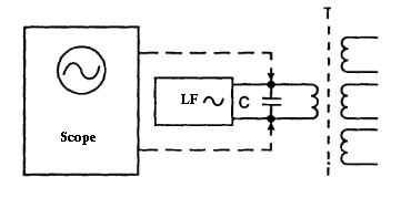
One way to test is to measure the inductance of windings and compare them to values in specifications. Still, not everyone has the ability to measure inductance, and not always you have transformed specifications near by. So there is another way to test pulse transformers, which may be acceptable to almost everyone radio-hobbyist, using a low-frequency generator that works at the resonance frequency of contour, which consists of external capacitor and pulse transformer winding.

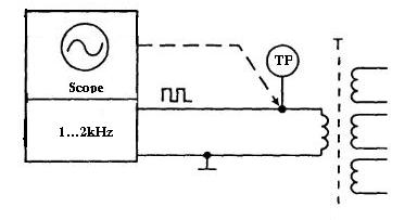
For this, you don’t even need a separate frequency generator as usually, it is a built-in oscilloscope for calibration purposes. Usually, this generator works at a frequency of 1…2kHz. But again, testing and finding resonance isn’t always handy. So another way is simpler. Connect the transformer to the generator as follows:

In this case, you have to measure the signal in the test point (TP). The differentiated signal on winding should have amplitude near to signal generator amplitude. Then pulse transformer can be considered OK; otherwise, if there are no pulses, then it can be that at least one winding is short-circuited.

It can be a situation that the measured signal amplitude is very low comparing to source signal amplitude. This is also a result of short-circuit in one of the windings.
Such a testing method is convenient because you can test pulse transformers without taking them out of the circuit. Disconnect or desolder one lead of primary winding and connect it to calibrating generator of the oscilloscope. According to measured signals, you can diagnose failures like diode failure connected to the secondary winding, or simply windings are short-circuited because of overheat and so on.


Good
a result of short-circuit in one of windings.
hi, very nice answer
this was really useful to me.