Such a multi-purpose device is a nice example of using a microcontroller for combined tasks. The idea of a radio-clock-thermometer came up when the author’s car audio head-end was stolen. He decided to use what’s left from the car radio and build something nice. So the project has started.
The intent was to use a radio module (KDC-2092) from Kenwood, but somehow it didn’t respond. So radio chip was taken from a computer radio tuner (TEA5757H), which can be easily controlled via 3 wires(DATA, Clock, Write Enable). Additionally, mono/stereo selection input is available. To give more control power, there was an advanced car audio signal processor, TDA7407D, used. The audio processors also can be controlled digitally via the I2C interface. The temperature reading was implemented with the DALLAS DS1820 sensor. As the datasheet says, there can be up to 8 temperature sensors connected to one wire, but only two were used in this project. Program piece of reading temperature sensors was adapted from https://frank.bol.ucla.edu/2313Temper8.htm.
Information is displayed on graphical LCD Powertip PE12864URT-003-IY1 128×64 with a built-in ST7565 controller. Data on LCD is organized as follows: 128 columns and 8 rows of 8 bits as dots. So for one screen, there are 8×128=1024 bytes = 1kB needed. All images and fonts were developed with Adobe PhotoShop 7.0 and made available to flash them into AMD29F010B flash memory (or smaller AT29C512). Flash memory can be programmed with WillemProg or another programmer. Flash memory is organized as follows: in address range [0000-00FF], all necessary LCD control commands are stored, further addresses store images and fonts.
The program for the AVR Atmega8515 microcontroller is written in Assembly language for AVR Studio.
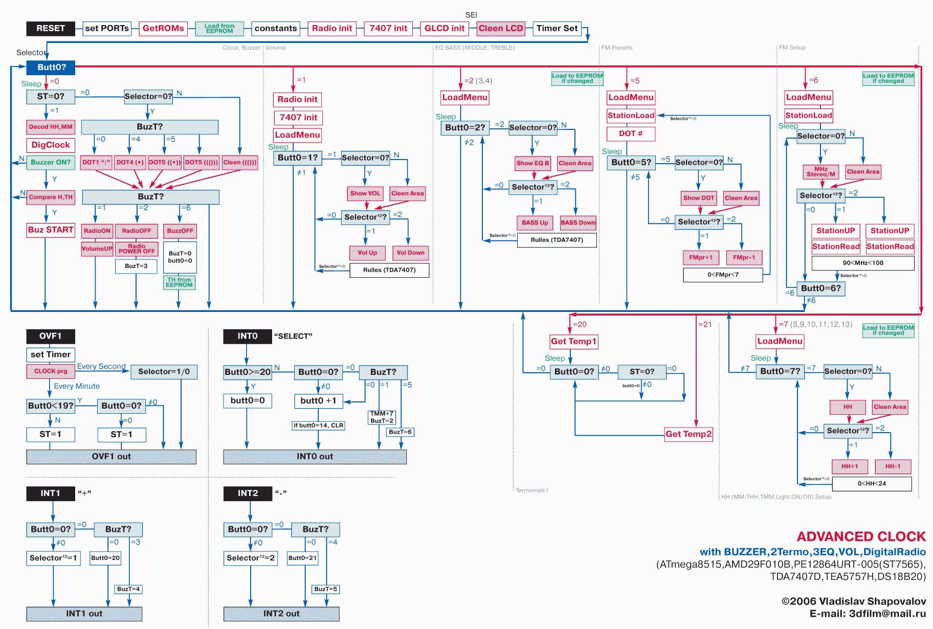
The main variable is the button <Select> counter (Butt0 connected to INT0 pin). Depending on the button press count related function is called. <+> and <-> buttons are used to increase and decrease parameter or select sub-function. Meaning of press counter values:
- Clock;
- The volume control also low, mid, and high freq control;
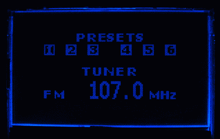
- Tuner settings, searching for radio stations, the station is assigned to a number and saved on exit from the menu;
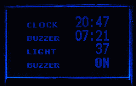
- Clock setting, alarm setting, LCD contrast, switching On/Off back-light;
- LCD OFF while other functions are working in the background;
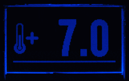
- Temperature display of two sensors controlled with <+> and <-> buttons.
When the alarm clock is set, a thin bar under time digits is displayed. When the alarm starts, its sound level grows up slowly. If the <Select> button is pressed, an alarm is reset +7 minutes ahead. Alarm is turned of completely by pressing buttons <Select> <+> and <-> in series. This should wake you up 🙂
All constant parameters are stored in microcontrollers EEPROM memory, so all parameters are preserved when power is turned off. When the clock is tarted – it loads initial parameters from EEPROM, including alarm settings, radio stations. The clock also has a protection circuit from power loss. It uses a supervisor IC(MC34064P-5), which monitors a voltage level. It gives a 0 to pin PB7 when voltage drops below the threshold after this happens – LCD is switched OFF, all periphery is turned off the only clock is working from the internal battery (not tested).
CD4049 IC is used to remove button de-bouncing. Using External components allows saving processing time for faster response. As the controller goes to sleep every second, there is CD4042 IC used, which remembers the last stage of control pins. When MCU goes to sleep, ports enter the high Z-impedance stage, so the trigger has to keep control voltages for transistor key VT2.
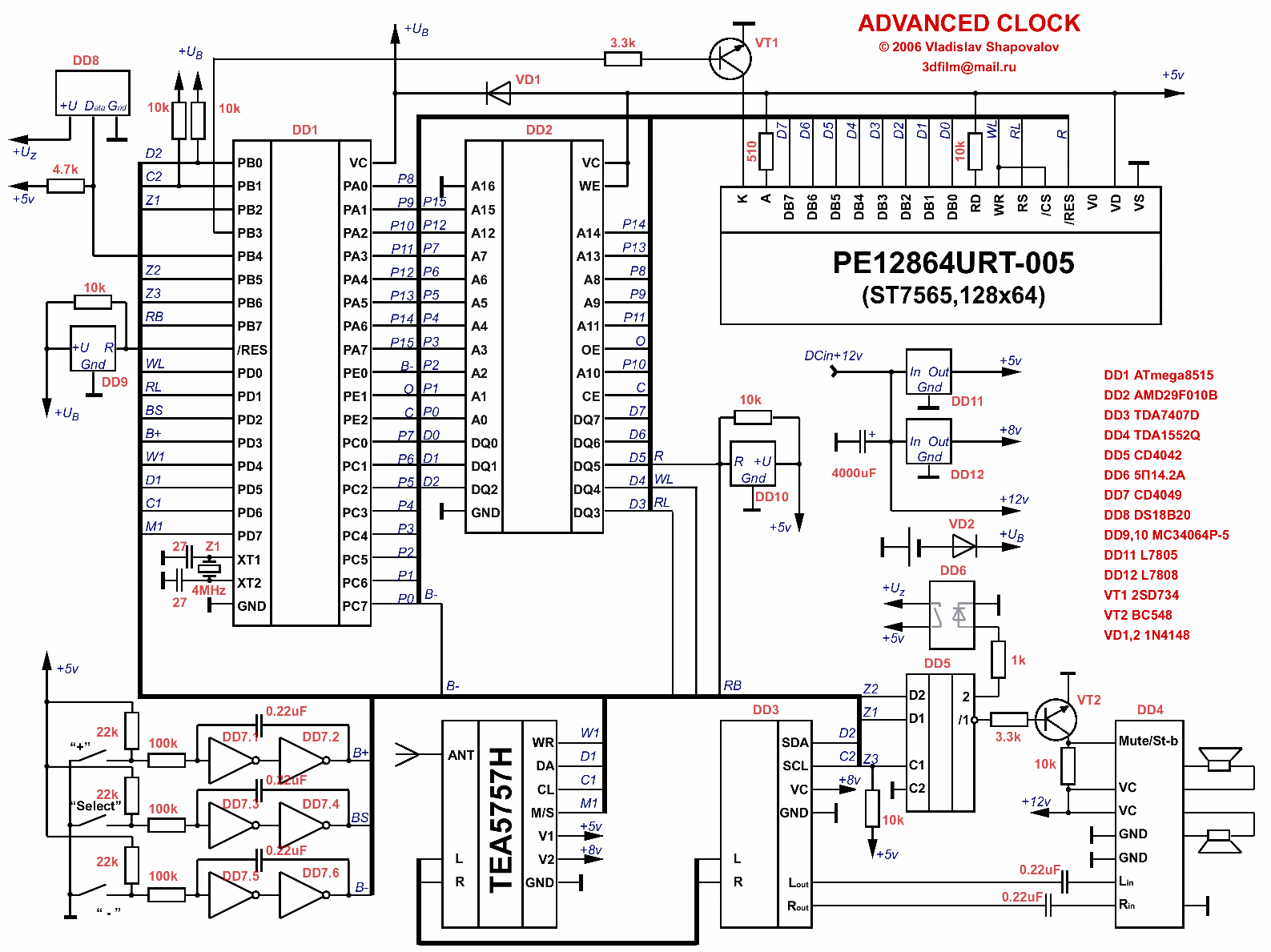
Circuit diagram:
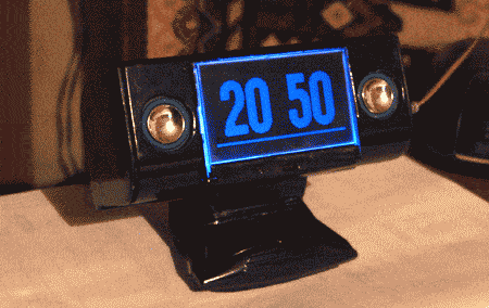
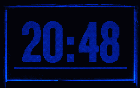
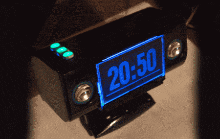
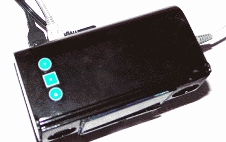
Few photos of working device:


Firmware and flash contents are Here.


Hey.
Very nice! Well done…
Hey man, I just attempted to e-mail you in relation to an issue I had regarding this post, however I can not fully find out a way to reach you. If however you can view my email address, can you send me a msg? Thanks man.