Why use watchdog variable timer

Most of the embedded microcontrollers contain watchdog timers. The watchdog variable timer is literally watchdog. The watchdog timer continuously inspects the program flow. Basically, if the microcontroller program hangs, then the watchdog timer resets it and brings the embedded system back to life. The idea is elementary. Let’s say, you know, that your program has to be executed during 20ms. And you know that the worst-case scenario is 30ms. Then you set the watchdog variable timer connected to the highest priority interrupt RESET. Once the Watchdog timer is triggered, the timer counts up to the time you set, and then it resets the MCU. The only way to avoid resetting is to send a command to the watchdog timer to start counting. Technically watchdog variable timer is nothing more than a retriggerable one-shot multivibrator.

Continue reading

How to use inline ASM using WinAVR

I have been working on the optimization of one of my C codes. I needed one function to be as optimal as possible. I decided to use inline ASM to achieve this. I decided to write a few lines about this. There are a few rules that are necessary to follow. Each ASM statement is divided by colons into 3(up to four parts): Assembler instructions part; A list of output operands (comma separated); A list of input operands (comma separated); Clobbered register – usually left empty.

Continue reading

Marking of AVR microcontrollers

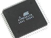
There is quite a big variety of AVR microcontrollers that ATMEL company produces. This article is about how to Extract information about the AVR microcontroller using its marking on the package. Each microcontroller has its own mark on the package: numbers and letters. The first is the microcontroller type. After follows, a suffix of three fields. The first field is one or two digits, which indicate maximal operation frequency MHz. The second field is a letter showing the package type. And the third field shows the temperature range of the working environment. There are a couple more marking letters “L” and “V” after the microcontroller type. This means that the microcontroller operates at low or very low voltages (and frequencies, of course).

Continue reading

AVR controlled DDS generator software writing

During my spare time, I am developing the program for the AVR controlled DDS generator. I decided to write software using the WinAVR tool-set. How far ahead I have moved with this? I have implemented: Menu system; Reading previous generator configuration from EEPROM; Setting signal mode; Storing last generator configuration to EEPROM to be loaded after reset; Four types of signal output (square, sawtooth, triangle, and sine wave); Things I still need to do: Ability to change signal frequency; Implement other signals (listed below); Make program clean-up;

Continue reading

Reading AVR button status using WinAVR

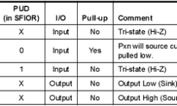
If you want to bring some interactivity to your embedded projects, one option is to add buttons. This allows you to control program flow, set parameters, and much more. Few words about AVR ports. AVR Port pins can be configured as input or output. See table for all general pin configurations: DDRx register is the so-called direction register; PORTx – is port output register; PINx – is pin input register;

Continue reading

Simple routine how to store data in microcontroller flash and read from it using WinAVR

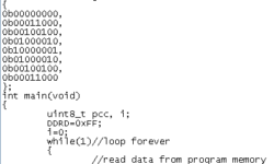
I’ve been asked about how to store data tables in flash memory using the avr-GCC toolset. I decided to post an answer here. Might be someone who find this useful. To demonstrate this I have set up a project using the VMLAB simulator. The files you can download from here: Small project using VMLAB simulator So I created a project in VMLAB. It will help if you read my previous article ho to do this: Using VMLAB as a virtual oscilloscope In project window I have connected 8 LED’s to port D by typing this: D1 VDD PD0 D2 VDD PD1 D3 VDD PD2 D4 VDD PD3 D5 VDD PD4 D6 VDD PD5 D7 VDD PD6 D8 VDD PD7 Then I wrote a simple C program: In program you see, that data can be stored in flash memory using data describing sentence: To make PROGMEM macro work you have to include library pgmspace.h. Bellow you see result of simulation in VMLAB environment:

Continue reading

Internal microcontroller ADC

Many microcontrollers contain internal on-chip ADC. Typical devices would be Atmel Atmega series microcontrollers like Atmega8 and further. Internal ADC is a successive way to integrate the analog world into your embedded systems using only one microcontroller die. Many applications don’t require high speed or high accuracy ADC conversions; thus, on-chip ADC is the best choice. Let’s look at Atmega8. It contains a 10-bit approximation ADC with an analog input multiplexer of 8-single-ended input voltage (refers to 0V) channels.

Continue reading

How to measure wind direction

I found this wind direction measurement circuit simple and interesting. If you are doing some home automation project, this might be another sensor included in your project. For Wind direction measurement, you will need a circle from some material (you might even use a CD.) Then stick an arrow on top. One end of the arrow should have a fin. Another end of the arrow should have a piece of magnet. Then put eight magnetic sensors around the circle in the magnet’s way. See drawing:

Continue reading

Creating custom LCD characters using WinAVR

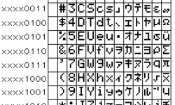
Standard LCD modules come with built-in Character MAP stored in LCD ROM memory. There are plenty of characters for your needs, but you may still need some special ones like backslashes or some symbols in different languages. This LCD has a reserved RAM area for storing eight 5×7 dot matrix character patterns. In the table above, this area is in the first column with addresses starting from 0 to 7 (from 0b00000000 to 0b00000111). This means that you can define any characters in these 8 fields as you like and use them by calling them by addresses from 0 to 7.

Continue reading

Always read newest datasheets

Reading of datasheets is or should be an important part of designing electronic devices. Reading datasheets is necessary for writing device requirements, planning budget, and selecting suitable components. Datasheets of each component may be found in manufacturers website. Once you’ve selected a suitable component, be sure that you read the datasheet and understand everything in it. Otherwise, you may miss some critical parts that could ruin all your plans. It is better to find errors before you start designing than after. Another important issue is that always check for newest datasheets and errata – datasheet bug lists. It is not good practice to use your old datasheets from your hard drive archive or other places. These datasheets may contain bugs. Just download the newest microcontroller or other semiconductor datasheet and compare to yours downloaded let’s say a year ago. Errata’s and datasheet changes are usually listed at the end of the datasheet. You may look at this and find out what would you miss with old datasheets. The electric characteristics maybe are the same, but there may be configuration bugs or even discovered bugs in hardware and proposed workarounds to avoid them. So be critical and don’t rely blindly on…

Continue reading