Today most electronic equipment consists of signal generators and processing units. These units are connected with transmission lines. These lines have a big influence on signal distortions. On these lines depends transmission lines stability. Let’s see how transmission lines affect transmitted signals.
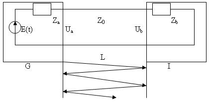
(G- signal generator; Za– output impedance; I- signal receiver Zb– input impedance; L- transmission line length; Z0– Line impedance.
When line is tuned and without losses then input voltage:
Ub(t) = ZbE(t-t)/(Za + Zb)
E(t)- generators signal amplitude; t- signal delay in line.
t =l/v ;
l- line lenght; v- signal speed.
If the line is not tuned up, then there are distortions in line because of reflections inline:


If signal E(t) is step function:

Then signal in line exit in discrete time moments will be:
U(0) = p;
U(t) = p*(1+pb)
U(2t) = p*(1+pb+pa*pb)
U(3t) = p*(1+pb+pa*pb+pa*pb^2);
U(4t) = p*(1+pb+pa*pb+pa*pb^2+pa^2*pb^2);
U(5t) = p*(1+pb+pa*pb+pa*pb^2+pa^2*pb^2+pa^2*pb^3) …
where

Depending on reflectance coefficients and their signs distortions can differentiate or integrate:

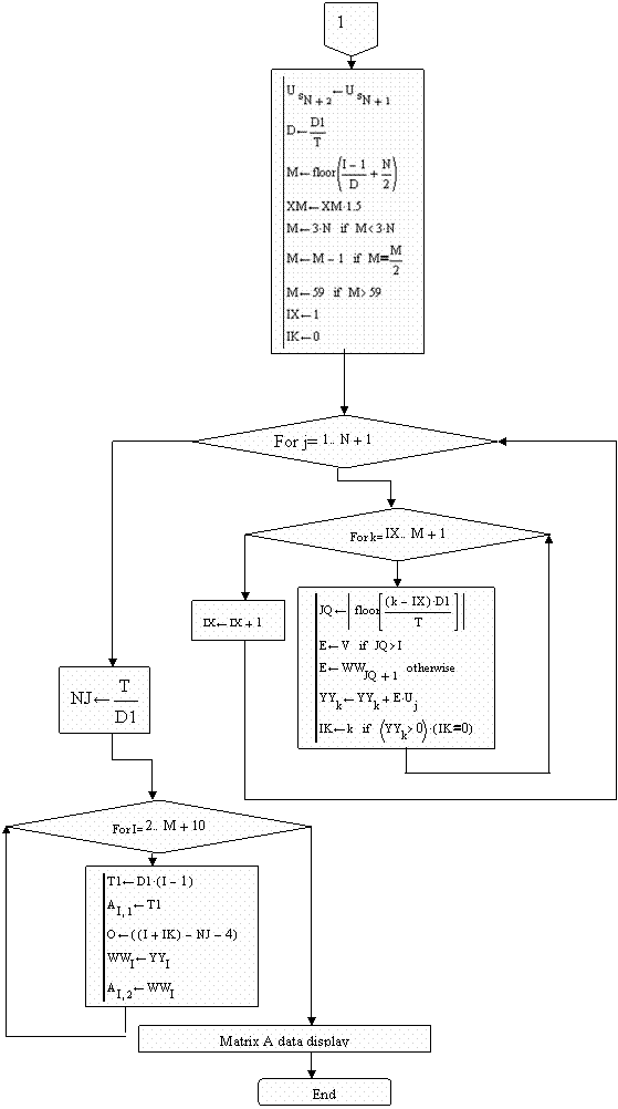
A real model using MathCAD was implemented to see how the signal looks on exit depending on parameters. Below you see used algorithm structure used in modeling:
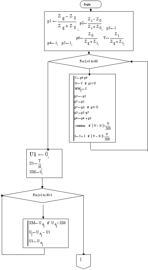
Part 2:
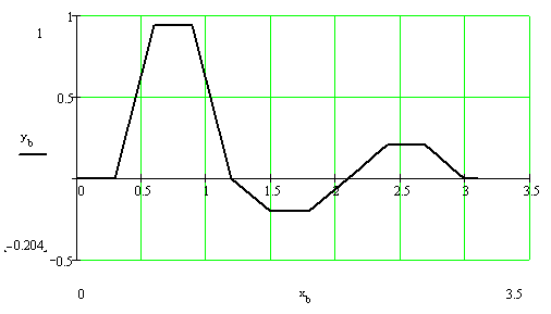
One of results using trapezoid signal:
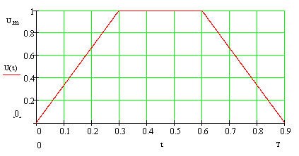
In exit we get distorted signal.
Download your MathCAD Transmission Line (13, 12, and 2001i versions ) file to test various parameters and different signal shapes.

