We know that digital signals are stored as binary numbers in memory cells. Let’s see how these digital signals can be transferred, in other words – how they can be encoded into electrical signal shape. When the signal has to be sent, it has to be modulated.
Pulse Code Modulation (PCM)
Probably the simplest and the most common modulation method is pulse code modulation (PCM).

In CPM, coding information is modulated as voltage levels. If the supply voltage is 5V, then binary”1″ is represented as +5V while 0 as 0V level. Only two voltage levels are used to modulate the signal. The signal can be sent in parallel (bus mode) or serial mode. In parallel mode whole (let’s say 8 bit) signal can be sent at once via 8 wires, while in serial mode, data has to be sampled in time. This transmission method is most popular in embedded systems. For instance, ADC sends converted data to DSP using CPM. CPM method is OK, but it has several drawbacks like the number of wires required for parallel buses. Still, probably the most dangerous problem is that transmission may experience skew problems when each data wire may have different time delays because of geometrical differences. Especially when data rates are high – all bits may not arrive simultaneously to the receiver what may lead to errors. So CPM encoding method is mainly used for short distances. Of course, the serial method is used instead of parallel, but then we are losing speed. On the other hand, we are saving space in PCB because only one wire is needed.
Serial transfer mode has more possible modulation methods like PAM, PPM, PNM, PWM, and PDM. Each of them has a different schema.
Pulse Amplitude Modulation (PAM)
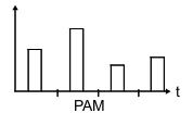
During PAM modulation, the actual amplitude of the pulse represents the number being transmitted. This is similar to analog signal transmission, but it is discrete in time.

Pulse Position Modulation (PPM)
During PPM transmission, signal pulses are fixed width and amplitude, but the actual number is represented by pulse position in time.

Pulse Number Modulation (PNM)
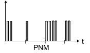
In this case, the digital number is represented by several pulses in a given time slot. Signal width and amplitude is fixed.

Pulse Width Modulation (PWM)
This is a more common encoding method in power and motor control. In this case, pulse width in a given time period represents the number being transmitted.

Usually, in PWM mode, the signal amplitude isn’t interesting as it is a fixed value. But in some cases, the second information value can be carried as amplitude. In this case, we get a combination of PAM and PWM – the simplest way to achieve this is to multiply PWM and PPM signals.
Pulse Density Modulation (PDM)
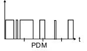
In the PDM case information, the value is represented as signal period (frequency). In other words, the digital value is represented by pulse density.

To achieve one or another modulation, there has to be some standardization needed. To transmit and receive signals properly, there are CODEC (coder-decoder) chips used. CODECs may be separate chips or integrated into microprocessors and microcontrollers. Usually, they operate at the hardware level, and you don’t need to take care of signal formation. Probably most common is the PCM modulation interface. All processors and other digitals devices have PCM interfaces that can handle this type of signal.

