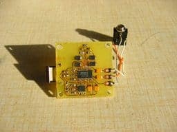
Have immensely interest in the audio DAC design, and would like to DIY a low cost but powerful audio DAC? Ok, now you have the chance, as you’ll learn to create your very own audio DAC today.
You will use the circuit PCM2902 for this project, where you will need to design the DAC from USB with this circuit on a one-sided PCB! Since the circuit board is a well designed wrong board, everything besides the crystal and USB connector will be placed from the bottom.
Below here is the schematic diagram from datasheet of PCM2902.

This circuit includes DAC, ADC, SPDIF output and input, and HID part, which has three buttons for the MUTE, VOL+, and VOL-. However, for this project, you only need to use the DAC part. The External low-drop voltage stabilizer is needed for high-quality playback in the DAC part. For this purpose, you can use the LP2951CM. Remember, the output voltage needs to set to about 3.7V with two resistors.

The circuit board is well designed to ground placement and separating the analog and digital ground. Moreover, these grounds are connected at one point at the USB connector.

