Consider PWM signal

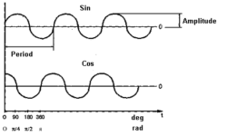
When using a microcontroller and want to drive motor control or controlled intensity, you can use DAC to generate an analog output voltage. But there is an easier way of doing this. You can use a digital output to reach the same results. This technique is known as PWM -Pulse Width Modulation. In this picture, you can see a 50% duty cycle square waveform. The width of ‘0’ is equal to the ‘1’ level. This means if the signal amplitude is 5V, then the average voltage over one cycle is 2.5V. It is as though of hawing constant 2.5V voltage.

Continue reading

Simplest 128 atmega programmer

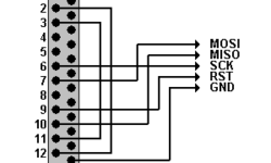
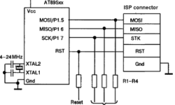
Atmega 128 is like other AVR microcontrollers. They are ISP – is in-system programmable. Earlier I wrote an article about an AVR ISP programmer where 74HC244 buffer is used. Using buffer is safer for your AVR. But what if you need 128 atmega programmers without any parts? Then you can connect your microcontroller directly to the LPT port or use protection resistors (220R) just in case. of course circuit works without resistors, but you put your LPT port at risk. Just connect GND, SCK, MISO, MOSI, and RESET to adequate LPT pins, and you can program atmega’s flash memory without removing it from a socket. Programming software can be PonyProg

Continue reading

Recognizing skin cancer symptoms using model based imaging

When a quality skin model is constructed – recognizing skin cancer symptoms can be more comfortable as many factors indicate the threat of skin cancer. Of course, this can’t give 100% results, as there are many shortcomings connected with skin lesion variety and interpretation errors. But some guides may help. Three main factors can indicate the risk of skin cancer. Recognizing skin cancer symptoms can be based on them. They are: Melanin presence in the papillary dermis; The thickness of papillary dermis; Blood behaviour around the lesion and inside it. The first important factor is the melanin present in the dermis. This is the main factor in recognizing skin cancer symptoms. If melanin spread in the papillary dermis or even dermis, this is a significant probability of being skin cancer symptoms, but not always. Several subfactors in this issue, like melanin spreading figure, depth, and melanin density within this shape. If there are more irregularities in the spreading area, there are more risks. Another factor in recognizing skin cancer symptoms is papillary layer thickness. In not going into deep too much there can be said, that the thinner this layer, the more significant risk.

Continue reading

First LPC2148 ARM7 microcontroller test – led blink

home made LPC2148 development board

This is simply a led blinking routine using my development board. The compiler I used was WINARM. I like this compiler because it’s free, and adaptation is easy while the same functionality is in WINAVR. This simple test blinks pin 16 of port 0. This I used when I first got to know ARM microcontroller. Here is the main code: All project files and compiled hex file is in LPC2148.zip.

Continue reading

TWI (I2C) interface on AVR

Two-wire serial interfaces are included in the following AVR microcontroller families: ATmega8x, ATmega16x, ATmega163x, ATmega32x, ATmega323x, ATmega64x, and ATmega128x. TWI interface is a “Philips” standard I2C. Using the TWI interface, you can connect up to 128 devices using only two wires: clock (SCL) and data (SDA). Only two pull-up resistors on each line are needed for this interface to work properly. The I2C interface circuit is an open collector. This means if one of all devices has a low-level signal on a line, then it is ‘0’, and if all devices have a high impedance state, then the signal is considered to be great ‘1’—more details about TWI interface you can find on any ATmega datasheet. One of my examples Interfacing AD7416 digital temperature sensor you can find here: Analog Devices Digital temperature sensor AD7416

Continue reading

Using buttons and switches with AVR microcontrollers

In most designs, you might want to put buttons and switches to control your program flow. This is not very difficult to read the button state. You can connect the button between pin and ground with an internal pull-up enabled. Then when the button is pressed, the pin value will be 0 when released – 1. Of course, you can use an external pull-up resistor. In fact, all mechanical contacts have their shortcomings – they generate multiple micro connections that can confuse AVR. The Delay of this effect depends on the quality of buttons or switches and can vary from 10 to 100ms.

Continue reading

Control 7 segment LED displays with AVR

LED displays are nothing more than sets of Light Emitting Diodes. The difference is that they have different shapes to display specific information. So driving LED displays is the same as regular LEDs. This is a simple connection when there are enough microcontroller Pins. But if you want to connect more displays, you will need more microcontroller pins than it can give you. Then it would help if you made a more advanced circuit with dynamic control.

Continue reading

Drive LED or Opto-isolators with AVR

This might seem very simple to many of you, but I still get questions about simple microcontroller interfacing. So I will put a thread of notes about interfacing AVR microcontrollers to devices like LED’s, relays, I2C, etc. As you might know, Diodes require a pretty small current. This current depends on diode type and can be from 3mA up to 20mA and more. Working voltage is from 1.5 to 4V. One AVR pin can sink up to 20mA of current; it is convenient to connect the diode directly to it with a current limiting resistor. Never connect the diode to the pin without a resistor – you may damage your AVR as your current may exceed the 20mA limit!

Continue reading

K-Type Thermocouples reviewed

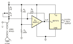
A thermocouple is a sensor that generates an electrical potential related to the temperature. The sensor’s operating principle is based on the fact that any electrical junction between two different metals generates an electrical potential that depends on the temperature and the metals used. The principle applies equally well if three metals are used. In that case, there are two junctions in series and the net potential results from the series addition of the two individual potentials. For example, if a copper iron junction is in series with an iron-tin junction, the net potential is the same as for a copper-tin junction. However, that is only true if both junctions are at the same temperature. The K-Type thermocouple is usually made of Chromel (+) and Alumel(-). The voltage generated from this sensor is 4mV/100°C. The max temperature that can thermocouple withstand is 1000°C without any damage.

Continue reading