
ChipKIT is an excellent substitution board for Arduino. It offers better performance as it is based on a PIC32MX320F128 microcontroller based on 32-bit architecture. The microcontroller has 128K of Flash and 16K of SRAM onboard. Having Arduino Uno shape factor, ChipKIT offers more than 42 programmable pins.

ChipKIT, like Arduino, can be programmed with a bootloader that communicates to the PC through USB-to-USART converter chip FT232RQ. Digilent has developed an STK500v2 based bootloader that works on PIC, so it is easy to program using the AVRDUDE tool. Besides that, they adapted an Arduino environment to work with ChipKIT boards. It’s called Mpide. It also supports Arduino boards, but it aims to program ChipKIT boards. Programming experience is pretty the same as for Arduino, and even most of the examples written for Arduino work on ChipKIT. This is true since there are no specific hardware elements touched like program memory or EEPROM. As you know, Arduino is rich in hardware support libraries as all shields are designed for Arduino. Latecomers like ChipKIT, even if they are hardware compatible, may have some difficulties with library integration due to the different architecture.
But with a little bit of effort, you can make everything work.
Today I am going to try to run the ITDB02 LCD module shield from iteadstudio.com.
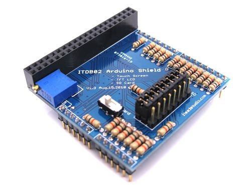
IT is an adapter for graphical color LCD with touchscreen/SD. Note! The touch screen and SC cannot work simultaneously due to the shortage of pins. Anyway, a little hack on ChipKIT would solve this problem. Let’s see what a starting point is. Henning Karlsen has excellently written libraries for Arduino and even for ChipKIT. But this library won’t work with the ITDB02 shield as it decided not to support this shield due to performance loss. Also, he claims that this shield is not optimized for a 3.3V power supply as there are resistors included. Instead, he offers to make a custom cable for interfacing LCD or use another shield for ChipKIT. I understand that move. If we look at ChipKIT pin layout we can see that Arduino compatible pins aren’t bit aligned as it is in Arduino:
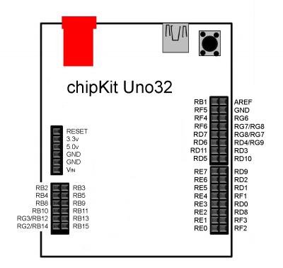
In Arduino, digital pins D7..D0 are all PORTD pins. So they can be controlled with a PORTD command that gives a significant increase in performance compared to individual digitalwrite() commands. ChipKIT, as you can see, has these pins scattered and cannot be controlled with port commands. Instead, you can see the inner pins of the header being aligned [RE0…RE7]. This is why another shield is offered that allows controlling LCD data pins with a single command. Anyway, I already have my ITDB02 shield on my table and want to make it work on ChipKIT. I’ve chosen to muck around with the Arduino library due to the same pin connectivity as a starting point.
The main problem with controlling LCD that we cannot use port commands here as port pins aren’t aligned. To solve this, I have written a simple function that takes data byte and scatters them to d0..d7 pins according to the layout:
void ITDB02::byteD0D7(unsigned char data)
{
  //ChipKIT pins DR9|RD2|RD1|RF1|RD0|RD8|RF3|RF2
  if((data)&(0b10000000)) digitalWrite(7, HIGH);
    else digitalWrite(7, LOW);
  if((data)&(0b01000000)) digitalWrite(6, HIGH);
    else digitalWrite(6, LOW);
  if((data)&(0b00100000)) digitalWrite(5, HIGH);
    else digitalWrite(5, LOW);
  if((data)&(0b00010000)) digitalWrite(4, HIGH);
    else digitalWrite(4, LOW);
  if((data)&(0b00001000)) digitalWrite(3, HIGH);
    else digitalWrite(3, LOW);
  if((data)&(0b00000100)) digitalWrite(2, HIGH);
    else digitalWrite(2, LOW);
  if((data)&(0b00000010)) digitalWrite(1, HIGH);
    else digitalWrite(1, LOW);
  if((data)&(0b00000001)) digitalWrite(0, HIGH);
    else digitalWrite(0, LOW);
}
This is the bottleneck of performance as each pin has to be set individually (read modify write operation), while in Arduino, there were PORTD = VH; Anyway, this workaround works. Also, I’ve changed control pin manipulation with digitalWrite() commands. And surely, as all font/image arrays are stored in SRAM, there is no need for pgm_read_byte() commands. We replaced it with array read statements.
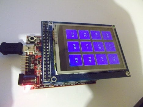
Arduino based Touchscreen library works on ChipKIT out of the box, so no modifications are needed.
Here are a few images of working LCD:

The next logical step would be to adapt the library for the SD card. But this will be next time.
Download project files: ITDB02_Shield_ChipKIT
The μLCD-32PT(SGC) 3.2” Serial LCD Display Module by 4D Systems is a true marvel, with it’s dedicated graphic processor. It uses the Serial1 port of the chipKIT UNO32 board (pins 39 and 40). Please find the full library at http://sites.google.com/site/vilorei/arduino/13–serial-touch-320×240-lcd-screen
I’m getting the same errors from Henning Karlsen’s libraries as from your library. I’m not sure where to start, so I was hoping for some advice, included are the errors:
ITDB02_Graph_ChipKIT.cpp:64:21: error: ‘uint16_t gamma [10][2]’ redeclared as different kind of symbol
c:\documents and settings\slinker\my documents\downloads\mpide-0023-windows-20120903\hardware\pic32\compiler\pic32-tools\bin\../lib/gcc/pic32mx/4.5.1/../../../../pic32mx/include/math.h:273:15: error: previous declaration of ‘double gamma(double)’
ITDB02_Graph_ChipKIT.cpp: In member function ‘void ITDB02::InitLCD(byte)’:
ITDB02_Graph_ChipKIT.cpp:176:46: error: invalid conversion from ‘double (*)(double)’ to ‘int’
ITDB02_Graph_ChipKIT.cpp:176:46: error: initializing argument 2 of ‘void ITDB02::main_W_com_data(char, int)’
ITDB02_Graph_ChipKIT.cpp:177:46: error: invalid conversion from ‘double (*)(double)’ to ‘int’
ITDB02_Graph_ChipKIT.cpp:177:46: error: initializing argument 2 of ‘void ITDB02::main_W_com_data(char, int)’
ITDB02_Graph_ChipKIT.cpp:178:46: error: invalid conversion from ‘double (*)(double)’ to ‘int’
ITDB02_Graph_ChipKIT.cpp:178:46: error: initializing argument 2 of ‘void ITDB02::main_W_com_data(char, int)’
ITDB02_Graph_ChipKIT.cpp:179:46: error: invalid conversion from ‘double (*)(double)’ to ‘int’
ITDB02_Graph_ChipKIT.cpp:179:46: error: initializing argument 2 of ‘void ITDB02::main_W_com_data(char, int)’
ITDB02_Graph_ChipKIT.cpp:180:46: error: invalid conversion from ‘double (*)(double)’ to ‘int’
ITDB02_Graph_ChipKIT.cpp:180:46: error: initializing argument 2 of ‘void ITDB02::main_W_com_data(char, int)’
ITDB02_Graph_ChipKIT.cpp:181:46: error: invalid conversion from ‘double (*)(double)’ to ‘int’
ITDB02_Graph_ChipKIT.cpp:181:46: error: initializing argument 2 of ‘void ITDB02::main_W_com_data(char, int)’
ITDB02_Graph_ChipKIT.cpp:182:46: error: invalid conversion from ‘double (*)(double)’ to ‘int’
ITDB02_Graph_ChipKIT.cpp:182:46: error: initializing argument 2 of ‘void ITDB02::main_W_com_data(char, int)’
ITDB02_Graph_ChipKIT.cpp:183:46: error: invalid conversion from ‘double (*)(double)’ to ‘int’
ITDB02_Graph_ChipKIT.cpp:183:46: error: initializing argument 2 of ‘void ITDB02::main_W_com_data(char, int)’
ITDB02_Graph_ChipKIT.cpp:184:46: error: invalid conversion from ‘double (*)(double)’ to ‘int’
ITDB02_Graph_ChipKIT.cpp:184:46: error: initializing argument 2 of ‘void ITDB02::main_W_com_data(char, int)’
ITDB02_Graph_ChipKIT.cpp:185:46: error: invalid conversion from ‘double (*)(double)’ to ‘int’
ITDB02_Graph_ChipKIT.cpp:185:46: error: initializing argument 2 of ‘void ITDB02::main_W_com_data(char, int)’
Any suggestion? I have the mpide-0023-windows-20120903 btw
this issue can be resolved by changing the variable name ‘gamma’ to some other variable name.
in ITDB02_Graph_ChipKIT.cpp:64:21 change
‘uint16_t gamma [10][2]’ to ‘uint16_t gamma2 [10][2]’
change all other instances of ‘gamma’ to ‘gamma2’ in the ITDB02_Graph_ChipKIT.cpp file.
I’m getting the same errors as shown in the comment above. I am assuming that there has been a fix for the gamma issue.
can anyone help with this problem?