I have got a couple of questions (in fact, not the first ones) for the AVR DDS generator I have built:
“that’s all the asm code that I don’t understand.
Could you explain it? Is it possible to do it with inline asm (only in C)?”
I decided to explain this part more deeply because it took me to figure this all out.
First of all, what we have to do, it is to implement simple DDS algorithm.
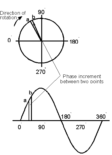
In a few words, Direct Digital Synthesis(DDS) is known as a Numerically Controlled Oscillator. Simple rule: NCO-based DDS is a point(memory location)-skipping technique (and a constant interpolation of the stored signal) and runs at continuous update(clock)-rate. As the DDS output frequency is increased, the number of samples per waveform cycle decreases.

Practically speaking, let’s have some math. We have a clock generator connected to MCU. In my case, F_CPU=16000000Hz. This is our Clock In.
Then we have sinewave map stored in rom:
const uint8_t sinewave[] attribute ((section (“.MySection1”)))= //256 values
{0x80,0x83,0x86,0x89,0x8c,0x8f,0x92,…
If we have 256 values of a sine wave for a single period, then at clock rate 16MHz, picking each value from the table, we would have max sine wave frequency Fsine=16000000/256=64kHz; This would be ok. But what if we need to have a sinewave frequency 1kHz or 1MHz. Then we need to implement some memory location skipping technique – this is what DDS does.
If we would like to have 128kHz instead of 64kKz, we would pick every second sample from the sinewave ROM map (128 samples). And if we would like to have 32kHz, we would have to make a delay after each sample and so on. DDS makes this much easier by having a Phase accumulator.

In my case, the phase accumulator is a 24-bit variable. Phase accumulator is calculating the address to sinewave table. Now all matters only in delta phase adder calculation: First of all, calculate output frequency resolution:
fres=(F_CPU/(clocks for one sample output))/2^(accumulator length) = 16000000/9/2^24=0.1059638129340278Hz.
Now it is simple to calculate phase accumulator adder value. If we need signal frequency
Fsignal=Acc_adder*fres;
For instance, if you need 1kHz output, then;
Acc_adder=1000/0.1059638129340278=9437.18399(9)=9437.
In my code I have used value frequency to calculate phase accumulator adder:
temp=frequency/RESOLUTION;
tfreq1=(uint8_t)(temp);
tfreq2=(uint8_t)(temp>>8);
tfreq3=(uint8_t)(temp>>16);
In pure assembly language this should look like:
ldi    r31,hi8(sinewave)   ; setup Z pointer hi
ldi    r30,lo8(sinewave)   ; setup Z pointer lo
; clear accumulator
ldi     r29,0x00        ; clear accumulator
ldi     r28,0x00        ; clear accumulator
; setup adder value  to 1 kHz
ldi     r24,tfreq1      ; tfreq1->r24
ldi     r25,tfreq2      ; tfreq2->r25
ldi     r26,tfreq2      ; tfreq2->r26
LOOP1:
add     r28,r24         ; 1
adc     r29,r25         ; 1
adc     r30,r26         ; 1 (Z pointer updated)
lpm                     ; 3 (load for sinewave table)
out     PORTD,r0        ; 1 (out to D port)
rjmp    LOOP1           ; 2 => 9 cycles
I think the ASM code explains why it is hard to do in only C language – it is hard to control the number of cycles in the main loop. Compiler output code may differ from expected and may not be optimal. It’s all about performance. You can implement a DDS algorithm in C language, but this probably would lower frequency resolution than in-line ASM.
Let’s start by explaining Inline ASM I have used. Inline ASM is the same ASM language, but it has to be written with some rules that the compiler could understand. There are many things you have to have in mind like using static inline function declaration and so on.
For in-line ASM read https://www.nongnu.org/avr-libc/user-manual/inline_asm.html
void static inline signalOUT(const uint8_t *signal, uint8_t ad2, uint8_t ad1, uint8_t ad0)
{
asm volatile( “eor r18, r18 ;r18<-0” “\n\t”
“eor r19, r19 ;r19<-0” “\n\t”
“1:” “\n\t”
“add r18, %0 ;1 cycle” “\n\t”
“adc r19, %1 ;1 cycle” “\n\t”
“adc %A3, %2 ;1 cycle” “\n\t”
“lpm ;3 cycles” “\n\t”
“out %4, __tmp_reg__ ;1 cycle” “\n\t”
“rjmp 1b ;2 cycles. Total 9 cycles” “\n\t”
:
:”r” (ad0),”r” (ad1),”r” (ad2),”e” (signal),”I” (_SFR_IO_ADDR(PORTD))
:”r18″, “r19”
);
}
In this particular case I will use explain each line of code:
- void static inline signalOUT(const uint8_t *signal, uint8_t ad2, uint8_t ad1, uint8_t ad0) – This is function declaration which is called like signalOUT(sinewave,tfreq3, tfreq2, tfreq1); sinewave is lookup table pointer, tfreq3, tfreq2, tfreq1 – are 24-bit accumulator adder value split into 8-byte variables.
- asm volatile(“ ”); – this is how asm inline is included in code(volatile switches off compiler optimization);
- “eor r18, r18 ;r18<-0″ “\n\t” – writes 0 to r18 (“\n\t” – used for cleaner listing new line and tab);
- “eor r19, r19 ;r19<-0” “\n\t” – writes 0 to r19;
- “1:” – label;
- “add r18, %0 “ – means add (ad0) variable tfreq1 to r18 (tfreq1 is tied to register :”r” (ad0));
- “adc r19, %1” – means adc (ad1) variable tfreq2 to r19 (tfreq2 is tied to register :”r” (ad1));
- “adc %A3, %2” – means ADC (ad2) variable tfreq3 to r30 (tfreq3 is tied to register :”r” (ad2)) and %A3 means r30 that :”e” (signal) declares register pair Z tied to pointer signal;
- lpm – is obvious load byte to r0 from Z pointed the location of Flash.
- “out %4, __tmp_reg__” – means that %4 variable is declared by :”I” (_SFR_IO_ADDR(PORTD)); __tmp_reg__ is by default as r0;
- “rjmp 1b” – jump to 1: in unix style;
- : – defines output operands
- :”r” (ad0),”r” (ad1),”r” (ad2),”e” (signal),”I” (_SFR_IO_ADDR(PORTD)) – input operands
- :”r18″, “r19” – clobber lists (define register that is not passed as operands).
Last notice that declaring a simple function without static inline generates ASM code where pointer signal is passed not to R30:R31 register pair but R24:R25.

