Fractal antenna constructions
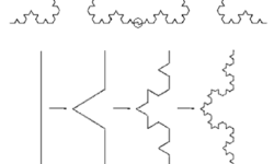
Among the usual antennas used in today’s data transfer, different types of antennas are used. First publications about electrodynamic characteristics of fractal structures were published in the 1980s, but the first practical approach appeared after 10 years. Dr. Nathan Cohen, professor of Boston University, designed, engineered, and patented many practical fractal antenna solutions and founded “Fractal Antenna Systems” in 1995. Van Koch fractal antenna As Nathan states, there were forbidden to use external antennas in the city in the center of Boston. Hence, he managed to hide the antenna within the design of an amateur radio station. He took aluminum foil and made an antenna as decoration according to Van Koch figure:

Continue reading

What are electrical switches principles and switching problems?

Switches are an important part of electronic systems. It is one of the most frequently used human interaction with electronic devices methods. But switches are the mechanical components that are a vital part of any equipment. Electrical switches Electrical switches are as old as electricity. The function is always the same – it makes or breaks current in a circuit. In early 19th switches were used for DC circuits, while later for AC and then they serves for switching wide spectra signals starting from audio and ending with digital. Well, switches have changed compared to those before 100 years, but the principle is the same old as the electric itself. When the switch connects the circuit path, it has a resistance of mOhm, and when the current path is broken, resistance is high MOhms and higher. This resistance and maximum voltage that can be applied to insulation is often a major important and vital feature that leads to switching stability.

Continue reading

Overview of noises in electronic systems

AVR DDS noise signal

There are several sources of noise in electronic systems. Noises are unwanted signals polluting random or not signals that reduce overall signal quality. Thermal Johnson/Nyquist noise Two scientists, Johnson, discovered this noise who did the experiments and Nyquist, who developed the formula. Thermal noise is present at all frequencies (has a constant power density at all spectra) and is called white noise. This noise can only be reduced by reducing the temperature, resistance, and bandwidth. Let’s see the Noise voltage RMSformula:

Continue reading

Multiple controllers in one design

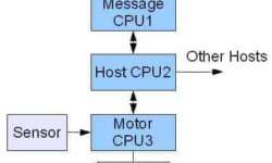
Actually, many embedded systems use multiple microcontrollers and microprocessors. This is not about multi-core processors but several distinct processors used in one design. Multiprocessor systems allow the distribution of computing power among different processors, and this way, overall speed may be increased, coding simplified, and modularity reached. Using multiprocessor embedded design has many benefits. One of them is modularity. Imagine a situation when a particular microcontroller-based subsystem needs to be installed only if a particular opinion is installed. Another, as we mentioned, is coding simplicity. Instead of writing and debugging one complex firmware, it may be broken into several distinct, easily manageable functions on different MCU’s.

Continue reading

Debugging embedded hardware and software traces

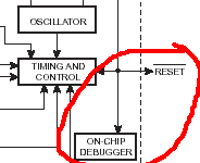
When designing an embedded project, we typically focus on the actual application but do not pay enough attention to the hardware and software debugging process. Adding the debugging capability to the project requires some strategy. Simple situation: hardware may not be installed but connected to another circuit when needed. So software must support the functionality regardless of whether or not hardware is installed. Another example may be Embedded inboard with multiple temperature sensors. Hardware should detect when the sensor is connected or disconnected without interrupt other sensors’ readings. One way of debugging is software trace(log) to provide historical information on what was happening if something went wrong. This technique is a good solution for developers who have no ability to use other debugging tools because of the following reasons:

Continue reading

Long range directional microphones-myth and reality

There are a lot of myths about directed long-range microphones. You can hear that they can reach distances of 100, 200, and more meters, others say that this is a myth and these numbers are for commercial purposes. Let us try mathematically to find proof and see the real situation. Introduction to long-range microphones When talking about directed microphones, we usually remember that sound sources are in the open air and have no reverberation effects. So the only factor is the distance of the sound source object from the microphone. Along with the distance, sound power drops significantly, and in longer ranges, it interferes with other sounds like wind and other noises in the atmosphere. When the distance is about 100m, sound pressure drops more than 40dB(compared to a distance equal to 1m). If the sound level is 60dB, then from 100m, you will hear 20dB. The sound level of 20dB is less than other environmental noise, and many standard microphones are not sensitive enough for such sound levels. So we can say that directed microphones must have: Complying with these requirements with one microphone is quite a difficult task. Other solutions were creating low directive microphones with high sensitivity…

Continue reading

Control LPT port under windows XP using Delphi

Another way of controlling the LPT port under Windows 2000 and XP is using the Delphi language. In this case, library, inpout32.dll, is used, which allows controlling LPT port registers. And now how to do this from the beginning. Start Borland Delphi 7.0 and make a simple form where you can enter Data to be sent to the port, Port Address, buttons for writing to and reading from a port. If you are familiar with building forms this should be ease task. Okay, now let’s start programming; first of all wee need to include inpout32.dll in the project. For this, Delphi has several ways, but let’s stay to the easiest one when the library is in the same directory, where the project is. The header in section uses we have to place function prototypes Out32 and Inp32 with special compiler directive external, saying where to find this function.

Continue reading

Controlling external devices using COM port communications programmed using VB language

There are a lot of Radio amateurs that want to control external devices using computer standard ports. One of them is the COM port. Everybody wants things to be easy as people doing electronics are more hardware people, not software. COM port is more often used than LPT because COM port is more resistive to bigger loads, and there are fewer chances of failing. So if you know Visual Basic a little bit, then this shouldn’t be tough to use the MSComm Control component, located in Project->Components. You should check box MSComm Control. Later you have to add this control to the form and write some code for it.

Continue reading

Understanding and conversion different firmware file formats

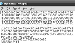
Without getting too deep in discussions about why there are several firmware formats and extensions used. But the fact is that you can face firmware files with extensions like BIN, HEX, or E2P. Let’s see how these files look like and how to convert between them. First of all, it is important to mention that all firmware files can be one of two types: Text files contain ASCII symbols (codes from 32h to FFh); Binary files contain all ASCII symbols including nonprintable symbols (00h to FFh). First advice – never rely on file extension as it can be any. All are inside the file. So how to define what’s inside the file and what format? One easy way is to open a file with a notepad and see how the contents 犀利士 look inside. Continue reading

Continue reading

1-Wire protocol simple and easy

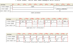
Dallas Semiconductor, owned by Maxim, developed the 1-Wire communication protocol. This protocol allows the communication of multiple chips to one host with minimal pin count. The protocol is called 1-Wire because it uses 1 wire to transfer data. The 1-Wire architecture uses a pull-up resistor to pull the data line’s voltage at the master side. 1-Wire protocol uses CMOS/TTL logic and operates at a supply voltage range of 2.8 to 6V. Master and slave can be receivers and transmitters, but only one direction at a time. LSB goes first always. Time slots transfer data in the 1-wire network. For instance, to write logic “1”, the master pulls the bus low for 15us or less. To write logic “0,” the master pulls buss low for at least 60us. The system clock is not required as each part is self-clocked and synchronized by the falling edge of the master.

Continue reading