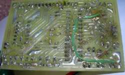
AVR controlled signal generator-skeleton board

This is continuing of thread AVR controlled signal generator. In earlier post 1 layer PCB prototype, I described a little about making this small project’s PCB. Now a few words about soldering and making the first test run. >This is my PCB board’s bottom. During soldering, I discovered one mistake – ISP headers pin MISO and MOSI were swapped. So I had to do some fixes (the green wire). Another small problem I discovered was that I couldn’t find 20k SMD resistors for my R-2R leader. For this DAC R-2R leader, I need 10k and 20k resistors to make DAC work properly. So I decided to make “fun” with my Board and soldered 10k SMD resistors in series to gain 20k:

