Telephone units are ubiquitous. They can be found in almost every house. In some houses with many rooms, a line is paralleled so that anybody can receive and make calls from different rooms. Their presence could be used for other purposes instead of making call per se. This module’s application can be found in the smart home automatic system incorporating a telephone unit as an input module. Using a telephone unit, somebody can control a remote system, as far as the telephone line can reach. To do so, such an interface between the telephone line and the control system is needed. DTMF Detector 2.0 is designed for this purpose.
Description
DTMF Detector 2.0 is a microcontroller system extension module that detects TMF tones and then decodes the tones into coded binary digits. Using DTMF Decoder, the 2.0 design engineer could interface the analog signal of the telephone line with the microcontroller system’s digital logic in a straight-ahead manner.
Module Specifications
The module specifications are as follows:
1. Input: DTMF tones from telephone line (analog signal)
2. Output: Decoded binary digits which correspond with DTMF tones.
Block Diagram

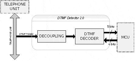
Figure 1 shows the block diagram of DTMF Detector 2.0. The module consists of a decoupling block and a DTMF Decoder block.
When someone presses a number, the phone unit encodes the number into two unique frequencies (DTMF) [3]. DTMF Detector 2.0 taps the telephone line to catch the DTMF tone being sent.
The decoupling block interfaces the telephone line with the DTMF decoder. Using a 1:1 ratio transformer, DTMF tone signals in the telephone line would be decoupled electrically but magnetically coupled, with input signals in the module.
DTMF decoder block does the DTMF detection and decodes it into unique binary digits. A specific IC, CM8888, is used for decoding the DTMF tone. Actually, CM8888 has other features instead, such as Call Progress (CP) detection and DTMF generator. In this module, we only use the DTMF Receiver feature. CM8888 interface with microcontroller unit by 9-bit signals: 4 bits for I/O data and 5 bits for control signals. To make it works, additional circuits are needed, as mentioned in the datasheet. Refer to [1] for a detailed explanation of the circuit.
Tools
Primary tools used for design and implementation of 7-Segment-Board 1.0 are as follows:
1. Hardware
- AVR ISP Development Board (designed by Erwin)
- Atmel ATmega8535
2. Software
- Altium Design Explorer Version 7.2.85
- WinAVR 20050214
Schematic Capture
See the schematic file in the attached zip file (DTMF_detector.SchDoc). We use a single-ended circuit configuration for the input stage of CM8888. One signal control, i.e., N_IRQ, is separated from others to simplify cabling when we want to connect it to any microcontroller pin. The schematic is self-explanatory.
PCB Layout Capture
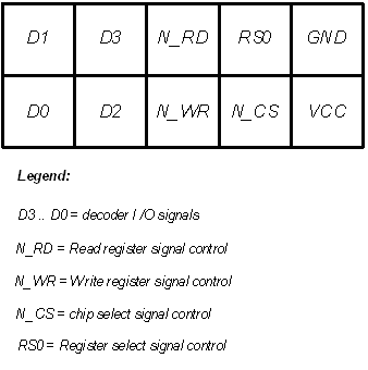
Please refer to PCB file in the attached zip file for (DTMF_detector_20060530.PcbDoc). Note that the physical board is implemented using a 1-layer PCB. Figure 2 is the picture of the physical board. Pin assignments for interfacing with MCU are shown in Figure 2. Table 1 gives us a list of module components.
Firmware Design
This project uses the Atmel AVR family microcontroller for driver implementation. No particular reason but tools availability that makes the decision. The module driver, written in C, consists of 4 separate files to simplify the maintenance: main.c, port.h, cm8888_drv.c, and cm8888_drv.h.


Table 1. List of Primary Components
| Component Name | Units | Notes |
| RJ11 Socket | 2 | Input sockets |
| CM8888 | 1 | DTMF Decoder |
| XTAL 3.579545 MHz | 1 | |
| 1:1 Transformer | 1 | Decoupling |
| Header 5×2 | 2 | Output |
| C 100nF Ceramic | 4 | Decoupling C |
| R100K 1/4W | 2 | Input Voltage Divider |
| R30K 1/4W | 1 | Pull up R for N_IRQ |
| R360K 1/4W | 3 | Steering Circuit |
The main.c file is the main program that is used to test and verify the driver. The port.h and cm8888_drv.h files are self-explanatory. The cm8888_drv.c contents 3 functions, that is:
void init_DTMF(void)
This function initiates the data direction register (DDRx) and Data Register (PORTx) of AVR ports. After that, the program does power up initialization by writing 0000b to all control registers, and then it set up the operating mode of CM8888. The procedure of power-up initialization is described clearly in [2].
unsigned char read_stat(void)
This function read the status register from CM8888. It is provided for debugging purposes.
unsigned char scan_DTMF(void)
This function is responsible for scanning the DTMF tone received. When the microcontroller unit receives logic low from the N_IRQ control signal, it’s time to execute this function. DTMF detection is converted into ASCII format, including the button * and # at the telephone unit keypad.
Testing and Verification
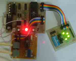
To do testing and verification, a simple program was made in main.c file. A LED board is used in PORTA as debugging tools. The program first initializes the module and supporting peripheral. Figure 4 shows the module under test.

The test result shows that all the DTMF tones received can be decoded into their unique ASCII number (Table 2). Figure 4 shows that the LED board displayed 0x35, which matched with the number 5 of the telephone unit keypad (MSB is on the bottom).
Table 2. Test Result
| Number | Output (hex) | Number | Output (hex) |
| 1 | 0x31 | 7 | 0x37 |
| 2 | 0x32 | 8 | 0x38 |
| 3 | 0x33 | 9 | 0x39 |
| 4 | 0x34 | * | 0x2C |
| 5 | 0x35 | 0 | 0x30 |
| 6 | 0x36 | # | 0x23 |
Portability
The source can be translated to other MCU (8051, PIC) with minor modification.
Conclusion
We conclude that both the hardware and firmware of DTMF Detector 2.0 are designed successfully.
Pieces of Advice
- To improve DTMF Detector 2.0, it is recommended to redo the layout, adding more free space between the nearest component. The components placement seems too cozy.
- For more cost-effective implementation, CM8870 can be used instead with minor modifications in hardware and software.
- To reduce unnecessary output header, N_CS can be tied to GND, and N_IRQ is included in one header.
References
- CM8888 CMOS Integrated DTMF Transceiver – datasheet. California Micro Device.2000
- MT8888 Integrated DTMF Transceiver with Intel Micro Interface– datasheet. Mitel Semiconductor. March 2001
- ATmega8535 8-bit AVR Microcontroller with 8 Kbytes In-System Programmable Flash – Preliminary datasheet. Atmel Corporation. June 2004
DTMF Detector: Documentation, Schematic and PCB design and example source code: DTMF Detector files
By: Ivan Christian adn Daniel Widyanto


Schematic in Pdf format
PCB in pdf format
Hi,
Could you please publish your circuit in pdf format? Protel is not available and we have no viewer.
Thanks