
Using relays are a common way of switching high-power loads with electronics. If you take any microcontroller or any other digital IC, you will see that their output current on a single pin is minimal – varies around 20mA. The same situation is with voltage. Digital pin output voltage is limited to IS supply voltage like 3.3v or 5V. Usually, we need to switch loads that draw significantly higher currents and are powered from a higher voltage supply.
And there, you have several options for switching loads. One and oldest method is using mechanical relays. They are still a trendy way of switching power electronics. One most significant disadvantages of using a mechanical relay is that it has moving parts with all rising problems. These are:
- slow switching time;
- relatively high control current;
- noisy;
- may produce sparks on switching;
- sensitive to environmental factors like vibration, humidity;
There is a more modern solution to overcome those problems – a Solid State Relay (SSR), also known as a single-phase power controller. Instead of switching loads mechanically, SSR does this with the help of electronics.
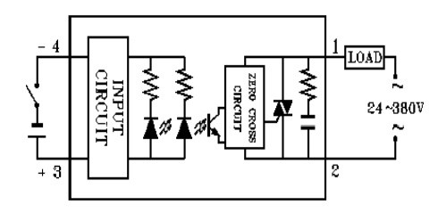
If we look at SSR-25DA internal circuit, we can see that the control circuit is isolated from the load by using optics. Usually, inside is an IR LED which turns on phototransistor controlling SCR (Silicon-Controller Rectifier). So the working horse of solid-state relay is SCR or TRIAC. Relay is triggered through a zero-crossing detector. This means that relay will be turned on only when the AC voltage crosses zero lines. This ensures that switching is always performed at the safest moment to minimize RFI noises in line. Relay also turns off when the AC voltage crosses zero lines. This is due to SCR properties.
As you can see in this particular relay, a snubber circuit is already included. It prevents the relay from unintended triggering due to voltage spikes on the AC line. Spikes usually appear from inductive loads. RC snubber circuit reduces those spikes to ensure safe and reliable operation of SSR. Other solid-state relays don’t have snubber circuit, so you need to include it externally – especially when switching inductive loads like motors, solenoids, or transformers like in https://myskyhawk.com/parts/ listings.
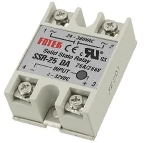
If we look at SSR-25DA solid state relay datasheet, we can see that it can switch 25A loads. Switching voltage is from 24V up to 380VAC with blocking 600VAC repetitive voltage. So it is safe to use on 240VAC line. What about triggering current and voltage. SSRs are great because triggering current is equal to LED current. So if your electronics can light a LED, you can trigger the relay. SSR-25DA relay already includes a current limiting resistor.Additionally, it also houses an indicator LED. Other SSR relays need an external LED current limiting resistor, which may not have an indicator LED. Our relay can be turned on from 3V to 32V DC signal and requires 7.5mA. 7.5mA is practically safe sourcing current for any microcontroller like AVR (Arduino), PIC, and even Raspberry Pi. No other external components are required, like the transistor switch for the mechanical relay.
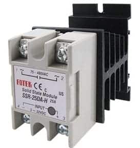
The last thing to discuss on SSR is power dissipation. Like any other electronics, they generate excessive heat. If you need to drive high current loads, it is necessary to ensure overheat protection. Best way to do this is to attach the heatsink to the backplate. Ambient temperature, load current and switching speed are the main factors that may cause overheating. At low currents (up to 5A for this SSR), the case is capable of dissipating heat. But if the ambient temperature is high enough, then you need to use a heatsink. How to calculate the safe margin?
Let us say we want to operate SSR at ambient temperature 40ºC. And drive 5A current. We know that SSR voltage drop is about 1.6V. Then we need to dissipate about 1.6V·5A=8W power. For semiconductors, we need to keep the junction temperature lower than maximum125ºC. Suppose we want junction temperature to be about 80ºC. From a similar datasheet, we can find that thermal resistance junction to ambient Ra = 10ºC/W. So junction temperature in our case:
Tj = 40ºC + 8W ·10ºC/W = 120ºC.
This is close to the maximum junction temperature. You can operate without heatsink if the load is switched in periods. Still, for constant driving, it would be better to use minimal heatsink to lower junction temperature and extend operating life.
I was wondering if it’s possible to use this Fotek 25DA SSR for dimming circuits. That is, can I drive it with an external 60Hz pulse timed to enable the SSR at specific AC phases?
The one parameter that seems to be critical with respect to average power output control circuits like the one I want to use is the minimum trigger pulse width. If this minimum is not low enough, the trigger pulse must remain on too long to be a reasonable control signal for turning the SSR on and off within a half cycle. Too long and you have no room to disable in the latter 50% of the cycle.
I’ve read the data sheet but I’m not an electrical engineer, so some of the numbers were a little cryptic. The one number I did notice was the minimum response time – suggested as “< 10ms", which seems like a very long time to me. A half US AC cycle is 8.33 ms, so it sounds like this device requires nearly full half cycle of trigger on state in to respond to the trigger.
No, you can’t trigger this at arbitrary phase, it is zero crossing triggered:-
“Relay is triggered through zero crossing detector. This means, that relay will be turned on only when AC voltage crosses zero line. This ensures that switching is always performed at safest moment to minimize RFI noises in line. Relay also turns off when AC voltage crosses zero line. This is due SCR properties.”
yes, sort of. this is close but i’m guessing you don’t want flicker in your load.
https://www.youtube.com/watch?v=hpADNRBDZ3Q
so you MAY be able to vary the duty cycle but you probably have to increase the frequency to do that. IF the Fotek 25DA SSR (or other SSR relay) will switch on AND off during the half cycles (otherwise it will probably flicker)
it could work.
if you’re REALLY ambitious and it does accept higher (than 60 Hz) frequencies (which i DIDN’T find and DIDN’T NOT find in the data sheet) then you may want to look into a 555 PWM circuit. like this (or similar)
https://www.youtube.com/watch?v=OXsu29K_Ap4
(jump to 7:00 for LED dimming)
which is what you’re doing inside the relay
Orrrrr… you can just use a Dimmer Switch which is basically IDENTICAL to PWM-ing the relay.