During my spare time, I am developing the program for the AVR controlled DDS generator. I decided to write software using the WinAVR tool-set. How far ahead I have moved with this?
I have implemented:
- Menu system;
- Reading previous generator configuration from EEPROM;
- Setting signal mode;
- Storing last generator configuration to EEPROM to be loaded after reset;
- Four types of signal output (square, sawtooth, triangle, and sine wave);
Things I still need to do:
- Ability to change signal frequency;
- Implement other signals (listed below);
- Make program clean-up;
Signals in AVR controlled generator:
- 0 – OUT_|¯|_ – square wave;
- 1 – OUT|/|/| – sawtooth;
- 2 – OUT|\|\| – reverse sawtooth();
- 3 – OUT/\/\/\ – triangle);
- 4 – OUT~~~~ – sine wave);
- 5 – OUT-NOISE – noise signal();
- 20 – PWM-OCC – timer output compare mode();
- 21 – PWM-SINMDS sine wave modulated PWM();
- 22 – PWMSQSMDS – sine wave modulated PWM. PWM positive, SQ negative polarity();
- 23 – PWM-CMDS – custom PWM. Will be possible to set custom duty cycle();
Signal generation
Square, sawtooth, triangle, and sine waves are generated by reading values from flash memory. The fragment of the sine wave is as follows:
//-----------------------------------------------
//signals saved in flash memory
const uint8_t sinewave[] PROGMEM= //256 values
{
0x80,0x83,0x86,0x89,0x8c,0x8f,0x92,0x95,0x98,0x9c,0x9f,0xa2,0xa5,0xa8,0xab,0xae,
0xb0,0xb3,0xb6,0xb9,0xbc,0xbf,0xc1,0xc4,0xc7,0xc9,0xcc,0xce,0xd1,0xd3,0xd5,0xd8,
0xda,0xdc,0xde,0xe0,0xe2,0xe4,0xe6,0xe8,0xea,0xec,0xed,0xef,0xf0,0xf2,0xf3,0xf5,
0xf6,0xf7,0xf8,0xf9,0xfa,0xfb,0xfc,0xfc,0xfd,0xfe,0xfe,0xff,0xff,0xff,0xff,0xff,
0xff,0xff,0xff,0xff,0xff,0xff,0xfe,0xfe,0xfd,0xfc,0xfc,0xfb,0xfa,0xf9,0xf8,0xf7,
0xf6,0xf5,0xf3,0xf2,0xf0,0xef,0xed,0xec,0xea,0xe8,0xe6,0xe4,0xe2,0xe0,0xde,0xdc,
0xda,0xd8,0xd5,0xd3,0xd1,0xce,0xcc,0xc9,0xc7,0xc4,0xc1,0xbf,0xbc,0xb9,0xb6,0xb3,
0xb0,0xae,0xab,0xa8,0xa5,0xa2,0x9f,0x9c,0x98,0x95,0x92,0x8f,0x8c,0x89,0x86,0x83,
0x80,0x7c,0x79,0x76,0x73,0x70,0x6d,0x6a,0x67,0x63,0x60,0x5d,0x5a,0x57,0x54,0x51,
0x4f,0x4c,0x49,0x46,0x43,0x40,0x3e,0x3b,0x38,0x36,0x33,0x31,0x2e,0x2c,0x2a,0x27,
0x25,0x23,0x21,0x1f,0x1d,0x1b,0x19,0x17,0x15,0x13,0x12,0x10,0x0f,0x0d,0x0c,0x0a,
0x09,0x08,0x07,0x06,0x05,0x04,0x03,0x03,0x02,0x01,0x01,0x00,0x00,0x00,0x00,0x00,
0x00,0x00,0x00,0x00,0x00,0x00,0x01,0x01,0x02,0x03,0x03,0x04,0x05,0x06,0x07,0x08,
0x09,0x0a,0x0c,0x0d,0x0f,0x10,0x12,0x13,0x15,0x17,0x19,0x1b,0x1d,0x1f,0x21,0x23,
0x25,0x27,0x2a,0x2c,0x2e,0x31,0x33,0x36,0x38,0x3b,0x3e,0x40,0x43,0x46,0x49,0x4c,
0x4f,0x51,0x54,0x57,0x5a,0x5d,0x60,0x63,0x67,0x6a,0x6d,0x70,0x73,0x76,0x79,0x7c
};
//-----------------------------------------------
The same is with square, sawtooth, and triangle. Each wave is stored using a 256 value table.
A signal is generated using a simple function:
//-----------------------------------------------
void signalOUT(const uint8_t *signal)
{
uint8_t i;
i=0;
do
{
PORTD=pgm_read_byte(&signal[i++]);
}while(1);
}
//-----------------------------------------------
Using this function, the maximum generated signal frequency was 6,25kHz. This means that one signal period consists of 256 values from the signal table. The crystal frequency is 16MHz. One value from the table requires 16000000/(6250*256)=10 clock cycles.
Changing the frequency of those signals should be easy. Just insert inside loop delay function regarding selected frequency. This I will do later.
I still don’t know if it is worse to try to increase the maximum frequency of the signal. Now it is 6,25kHz and takes 10 clock cycles for one byte from 256 to output. If I reached 5 cycles, that would be double frequency 12,5kHz.
In another hand, if higher frequencies are needed there will be a possibility to use a timer signal generator on output compare mode, but only square waves.
Now I am going to focus on implementing what I have planned and then think about optimization.
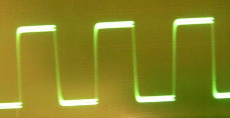
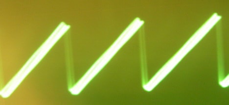
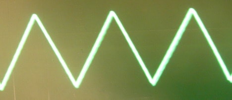
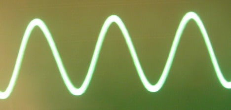
Bellow are signal pictures I have got at frequency 6,25kHz(picture quality is poor – I need to get a tripod for my camera):

Square

Sawtooth

Triangle

Sine wave
The source code of the current program is here: AVR controlled DDS generator software
Full documentation is on its way.


interesting… i have made some changes for me on this code.
maybee you are intrested in..
how do you want to change the frequency of the output?
I am comming with an improved code where I use DDS algoritm (use accumulator variable) where I can change frequency very easely by changing this value. This algorithm in this article is first one to test my hardware. I hope to finish this project very soon and publish it here.